Do you have a question about the King Industrial KC-70FX and is the answer not in the manual?
Keep dated proof of purchase for warranty and servicing purposes.
Replacement parts are available at authorized KING CANADA service centers across Canada.
A 2-year limited warranty is provided against defects in materials and workmanship.
Refer to the King Canada web site for the most updated parts diagram and parts list.
Read manual and labels to understand applications, limitations, and potential hazards.
Ensure the tool is properly grounded with a 3-prong plug and receptacle.
Maintain guards in good working order, properly adjusted and aligned.
Always check that keys and wrenches are removed before turning on the tool.
Keep the work area and floor clean and free of slip hazards.
Do not use power tools in damp/wet locations or expose to rain; ensure good lighting.
Ensure all visitors are kept a safe distance from the work area.
Use padlocks, master switches, or remove starter keys to child-proof the workshop.
Operate tools at the proper speed for better and safer performance.
Do not force the tool or attachment beyond its designed capabilities.
Avoid loose clothing, jewelry; wear non-slip footwear and hair covering.
Always wear safety glasses (ANSI Z87.1) and a face/dust mask if needed.
Maintain proper footing and balance at all times to avoid overreaching.
Keep tools sharp and clean; follow lubrication and accessory change instructions.
Disconnect tools before servicing or changing accessories/attachments.
Ensure the switch is in the "OFF" position before plugging in the tool.
Consult the manual for recommended accessories to avoid hazards.
Never stand on the tool to prevent serious injury if it tips over.
Check guards and parts for damage, alignment, and proper function before use.
Turn power OFF and wait for the machine to stop completely before leaving.
Do not operate the jointer until it is fully assembled and installed.
Never perform operations with the cutterhead guard removed.
Never start the jointer with the workpiece contacting the cutterhead.
Always use the fence to guide the workpiece; avoid free-hand operations.
Avoid hand positions where slips could lead to contact with the cutterhead.
Use blocks for material less than 3 inches high or thinner than 3 inches.
Do not plane material shorter than 10 inches or narrower than 3/4".
Never make cuts deeper than 1/8 inch; use 1/16 inch for wider cuts.
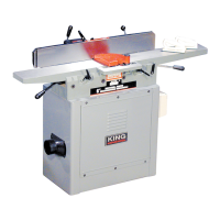
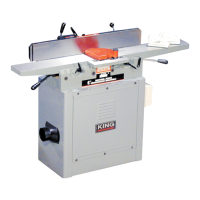
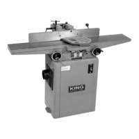
Connect the 6" jointer to a 120V, 15-AMP branch circuit with a 15-AMP time delay fuse/breaker.
Connect the 8" jointer to a 240V, 15-AMP branch circuit with a 15-AMP time delay fuse/breaker.
Ensure jointers are properly grounded via cord and plug in accordance with local codes.
Use proper gauge, 3-wire extension cords with grounding plugs and receptacles.
Unpack jointer, remove protective coating with kerosene, and wax unpainted surfaces.
Fasten jointer to stand using socket head cap screws or to a supporting surface.
Assemble fence carriage and sliding bracket to jointer base using provided screws.
Attach fence with pivot brackets to the sliding bracket using screws.
Attach rabbeting ledge to infeed table, ensuring it is level with the table surface.
Install cutterhead guard, ensuring it operates freely and does not bind.
Assemble motor pulley to the motor shaft, ensuring the hub is in the out position.
Place belt around pulleys and ensure motor and cutterhead pulleys are aligned.
Adjust motor position for approximately 1" deflection in the belt span.
Position and secure the cutterhead belt and pulley guard on the jointer stand.
Move and tilt the fence using lock levers and pins to desired positions and angles.
Adjust 90 and 45 degree positive stops on the fence for accurate angles.
Check and adjust the fence to be precisely 90 degrees to the table surface.
Check and adjust the fence to be precisely 45 degrees inward tilt to the table.
Check and adjust the fence to be precisely 45 degrees outward tilt to the table.
Adjust infeed table height and depth of cut using levers and stop screws.
Adjust outfeed table to be level with knives using levers and stop screws.
Carefully remove, replace, and reset jointer knives following safety precautions.
Adjust knife height so cutting edge extends .015" from the cutterhead diameter.
| Brand | King Industrial |
|---|---|
| Model | KC-70FX |
| Category | Power Tool |
| Language | English |