ADJUSTMENTS & OPERATION
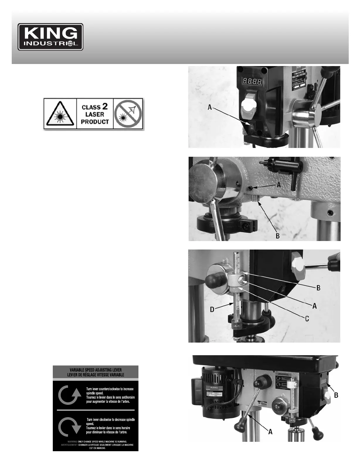
FIGURE 17
FIGURE 18
FIGURE 19
USING AND ADJUSTING DUAL LASER GUIDES
Warning! Do not look into the direct or reflected laser beam; can cause
eye injury up to 50 feet (15m) away. Class 2 lasers are considered safe
for accidental eye exposure. Do not look or stare into laser beam. This
is not a toy.
1) The dual laser guide system can be turned On/Off using the front
mounted laser switch (A) Fig.17.
2) Position your workpiece on the table and clamp it. Lower the drill bit
just above the workpiece. Turn on dual laser guide, The dual laser
guide laser beams must cross where the drill bit touches the
workpiece. If the dual laser guide laser beams is not properly aligned,
an adjustment can be made:
- Loosen set screw (A) Fig.18 using a hex. key. Turn laser tip (B) until
the laser beam is correctly positioned. Retighten set screw. Repeat
this step for the other laser guide on opposite side if needed.
USING THE DEPTH STOP
The depth stop mechanism Fig.19 allows repetitive drilling to an equal
depth, to adjust the depth stop mechanism:
1) Lower the downfeed handles until your cutting tool reaches the
desired drilling depth.
2) At the same time, push in the spring button (A) Fig.19 of the depth
stop setting nut (B) and move it against the head casting (C). The
depth stop scale (D) can also be used as a guide for setting the depth
adjustment.
3) Release the downfeed handles and check your adjustment.
CHANGING SPEED
This drill press has a variable spindle speed range from 580 to 3200
RPM. The spindle speed setting is conveniently displayed on the digital
readout on the head of the drill press. To change the spindle speed:
WARNING! Always adjust the spindle speed while the drill press is
running to avoid damaging the speed adjustment mechanism.
1) Turn the drill press on.
2) The spindle speed is controlled by the speed adjusting lever (A)
Fig.20 located on the left side of the drill press head.
3) Turn the lever counterclockwise to increase the spindle speed.
4) Turn the lever clockwise to decrease the spindle speed.
5) Refer to the digital readout (B) Fig.20 on the front of the drill press
head to set the desired speed.
FIGURE 20
 Loading...