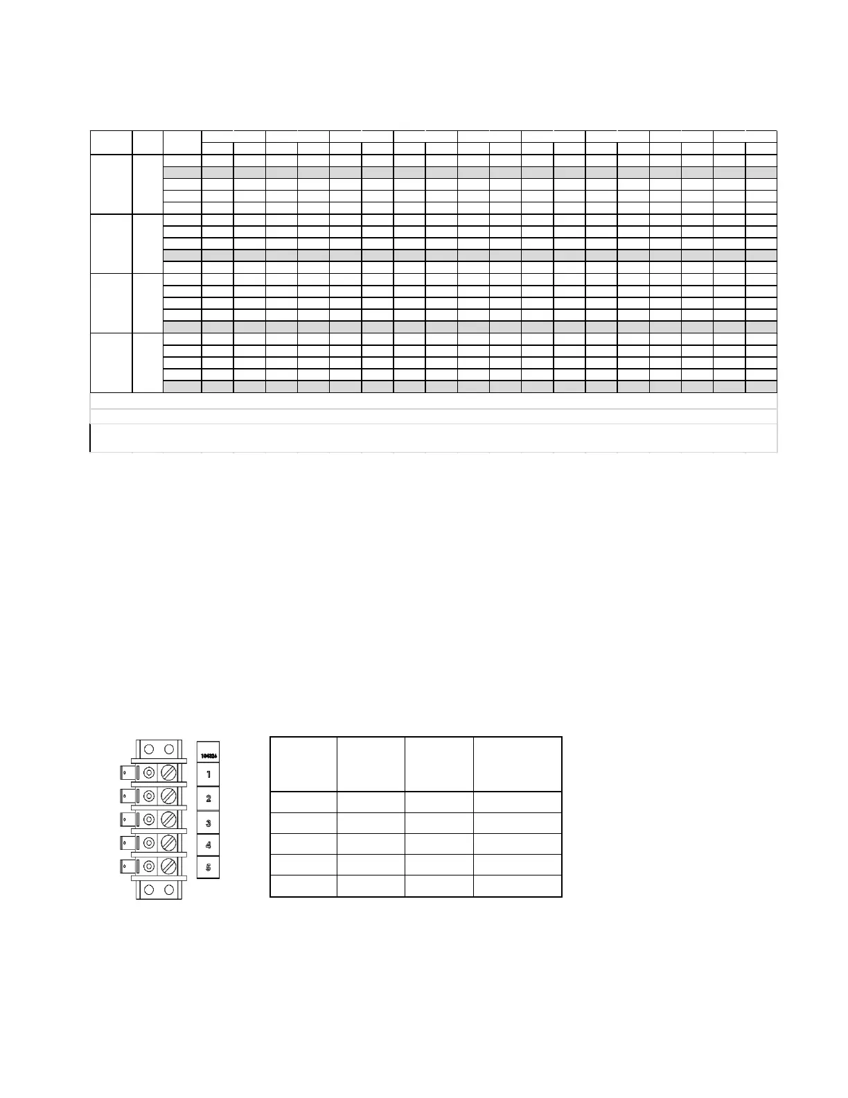
intended design criteria. Refer to the diagram below showing the terminal strip. The ECM motor is
CFM
RISE (F) CFM RISE (F) CFM RISE (F) CFM RISE (F) CFM RISE (F) CFM RISE (F) CFM RISE (F) CFM RISE (F) CFM RISE (F)
15.5 1,258 50 1,262 50 1,193 53 1,132 56 1,054 60 910 69 834 76 821 77 705 90
19.0 1,466 43 1,419 45 1,300 49 1,285 49 1,218 52 1,180 54 1,015 62 979 65 934 68
22.5 1,575 40 1,570 40 1,564 40 1,363 46 1,347 47 1,284 49 1,256 50 1,200 53 1,152 55
26.0 1,690 37 1,679 38 1,640 39 1,546 41 1,472 43 1,430 44 1,378 46 1,358 47 1,315 48
30.0 1,771 36 1,766 36 1,723 37 1,728 37 1,569 40 1,542 41 1,522 42 1,487 43 1,415 45
15.5 1,258 63 1,262 63 1,193 66 1,132 70 1,054 75 910 87 834 95 821 96 705 NR
19.0 1,466 54 1,419 56 1,300 61 1,285 61 1,218 65 1,180 67 1,015 78 979 81 934 85
22.5 1,575 50 1,570 50 1,564 51 1,363 58 1,347 59 1,284 62 1,256 63 1,200 66 1,152 69
26.0 1,690 47 1,679 47 1,640 48 1,546 51 1,472 54 1,430 55 1,378 57 1,358 58 1,315 60
30.0 1,771 45 1,766 45 1,723 46 1,728 46 1,569 50 1,542 51 1,522 52 1,487 53 1,415 56
15.5 1,258 75 1,262 75 1,193 79 1,132 84 1,054 90 910 104 834 NR 821 NR 705 NR
19.0 1,466 65 1,419 67 1,300 73 1,285 74 1,218 78 1,180 80 1,015 93 979 97 934 102
22.5 1,575 60 1,570 60 1,564 61 1,363 70 1,347 70 1,284 74 1,256 75 1,200 79 1,152 82
26.0 1,690 56 1,679 56 1,640 58 1,546 61 1,472 64 1,430 66 1,378 69 1,358 70 1,315 72
30.0 1,771 54 1,766 54 1,723 55 1,728
55 1,569 60 1,542 61 1,522 62 1,487 64 1,415 67
15.5 1,258 88 1,262 88 1,193 79 1,132 98 1,054 105 910 NR 834 NR 821 NR 705 NR
19.0 1,466 75 1,419 78 1,300 85 1,285 86 1,218 91 1,180 94 1,015 109 979 NR 934 NR
22.5 1,575 70 1,570 70 1,564 71 1,363 81 1,347 82 1,284 86 1,256 88 1,200 92 1,152 96
26.0 1,690 65 1,679 66 1,640 67 1,546 72 1,472 75 1,430 77 1,378 80 1,358 81 1,315 84
30.0 1,771 62 1,766 63 1,723 64 1,728 64 1,569 70 1,542 72 1,522 73 1,487 74 1,415 78
TAP NO.
 Loading...