2 3
1
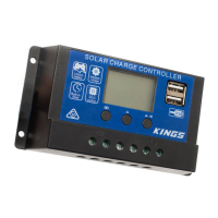
15A PWM SOLAR CONTROLLER
USER MANUAL
PLEASE READ AND UNDERSTAND THIS MANUAL
COMPLETELY BEFORE USING THIS PRODUCT.
AKSR-RG15A_01
V1.3
SAFETY
• Keep your Pulse Width Modulation (PWM) controller & battery away from any liquids
at all times.
• Keep the controller clean at all times (always check connectors to ensure they’re
free of grit before plugging them in).
• Do NOT use the solar controller to charge non-rechargeable batteries. Doing so may
result in harm to the user and/or damage the solar module, battery and controller.
Only use the provided solar blanket, regulator and adaptors/wiring provided in the
kit.
• All lead-acid batteries produce harmful, explosive gases. The battery should be
mounted in a well-ventilated area, as far as possible from any ignition sources. Do
NOT smoke or have a naked ame in the vicinity of the battery under charge.
• Never tamper with or pull any component of the regulator apart. Doing so will void
the warranty.
• The PWM controller is only suitable for regulating solar modules.
• The PWM controller is only suitable for lead-acid batteries: LEAD, AGM, GEL &
LITHIUM. The Solar Blanket & Controller should not be used with nickel metal
hydride batteries.
• Never connect more than 1 charging source to the PWM controller.
CONTENTS
1 x 15A PWM Solar Controller
Max Solar Input <50V
Float Charge 13.7V - Default, Adjustable
Discharge Stop 10.7V - Default, Adjustable
Discharge Reconnect 12.6V - Default, Adjustable
USB Output 5V / 2A
Dimensions 133 x 70 x 34 mm
Weight 154g
SPECIFICATIONS
OPERATING THE PWM CONTROLLER
PWM CONTROLS
Please note: not following these instructions may cause damage to the PWM controller.
Ensure that you attach the positive (+) and negative (-) wires to the appropriate terminals.
1. Connect the positive and negative wires from the battery into the terminals with the
battery icon ensuring polarity is correct.
2. The screen should turn on and display the battery voltage.
3. Connect positive and negative solar input into the two terminals with the solar icon,
ensuring polarity is correct.
4. The controller is now ready to use.
5. For additional load circuit, connect positive and negative wires to the terminals with
the lightbulb icon on the controller.
NOTE: Ensure a fuse is used on battery positive wiring to prevent short circuits and
potential damage to the unit or your vehicle.
Menu: short press: cycle through the different menu options; long press: conrm
selection or return to the main display
Up: increase value
Down: decrease value
MENU SCREENS AND THEIR FUNCTIONS
1. Press the menu button to cycle through the six different settings screens. Each
screen is explained below.
2. Holding the menu button for 6 to 7 seconds will allow you to change the settings on
a screen. Use the up or down buttons to change the values.
3. Hold the menu button again to conrm your settings.
MAIN DISPLAY
Displays details about voltage and connections
to the PWM controller. (Not pressing any button
for 10 seconds will return you to this screen.)
FLOAT OR CV VOLTAGE
Accept power from the solar panel until the
battery’s voltage reaches the set value.
Default: 13.7V
DISCHARGE RECONNECT
Connect to the load when the battery’s voltage
reaches the set value.
Default: 12.6V
MENU
UP
DOWN;
ON/OFF