KINROAD 150 SERVICE MANUAL VERSION 1, DEC., 2005
66
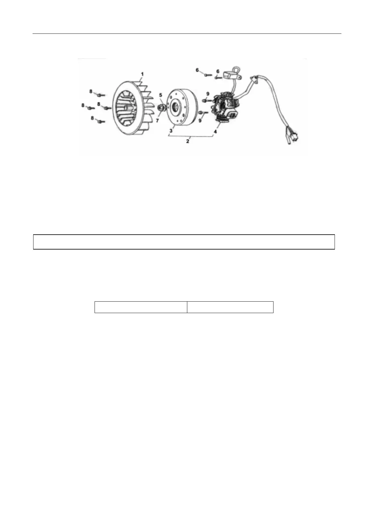
The picture shows structure of a common generator.
1. Cooling fan 6. Bolt
2. Generator assembly 7. Nut
3. Flywheel comp. 8. Bolt
4. Stator comp. 9. Bolt
5. Washer
PRIMARY COIL INSPECTION
Remove the 4-core connector of the generator.
Measure the resistance value between the white wire of the generator and connecting wire of the vehicle
body.
Standard value 0.2-0.4 Ω(20℃)
When the actual value is more than the standard value, the coil should be replaced.
GENERATOR REMOVAL AND INSPECTION
z The inspection work can be done on the engine, and there is no need to remove the generator.