2
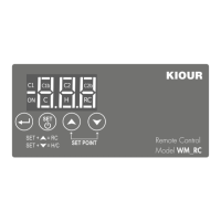
1. Press and the SPC parameter is displayed.
2. Press its value is displayed and with
or we change the SPC.
3. Press we enter the new value and the device works normally with the new setting.
1. Press to display the first parameter SPC. Press two times and the parameter Cod is displayed
2. Press to display its value and press
to enter the value 31. Press to store the value to parameter Cod.
3. Press again to exit the parameter menu all appropriate factory settings are now stored in the device..
On the room thermostat, pressing for 1 seconds SET+ , switches the mode from HEAT to COOL and opposite.
To activate or deactivate the device, press for 5 seconds It displays OFF.
ATTENTION : to gain full access to the parameter’s menu, the 3rd parameter Cod must be adjusted to 22 ( see parameter table at next page).
1. Press to enter the parameter menu.
2. Choose the parameter you want to adjust by pressing or and press to display it’s value.
3. Press or to change its value and then press to store the new value.
4. Press to exit the parameter menu.
Power supply: 12÷24VAC/DC / Maximum power consumption: 3W.
It is recommended using a power supply safety fuse: 0.5Α (not included)
Room temperature sensor NTC 10K 1% 25
o
C with temperature range -50÷+112°C (-58÷+230°F) IP68 (or PTC 1Κ 25
o
C temperature range -50÷+150°C
(-58÷+302°F) not included) / Accuracy: 0.5°C
Input modbus RS485
Relay 10A res. 250VAC NO -normally open- contact / Max current load 10Α
Connections with terminal blocks 18A using cable with cable cross section up to 2.5 mm² / It is recommended using a torque wrench with maximum torque 0.4Nm
Operating temperature: -15÷+55°C / Storage temperature: -20÷+80°C
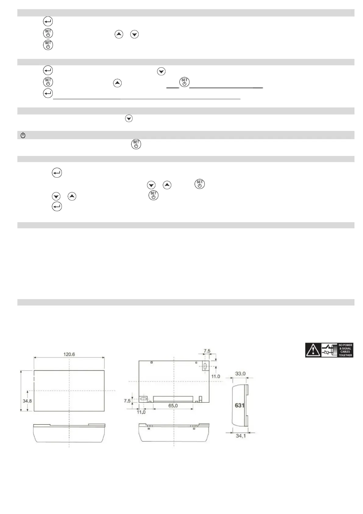
Dimensions 121x70x35mm / The device is wall mounted and is screwed to the wall with 2 screws / Protection IP20
Firmware: V1.1
ELECTRICAL DIAGRAM - DIMENSIONS
ATTENTION: according to safety standards, the device must be properly positioned and protected from any contact with electrical parts. The device must be fastened in such a way that it
cannot be removed without the use of tools. Disconnect the main safety switch of the installation before proceeding to any maintenance. Disconnect the power supply of the device before
proceeding to any maintenance. Do not place the device near heat sources, equipment containing strong magnets, in areas affected by direct sunlight or rain. Prevent electrostatic discharges
and sharp objects from been inserted to the device. Separate signal cables from power supply cables to prevent electromagnetic disorders. Signal cables must never be in the same pipe with
the power supply cables. ATTENTION: Read carefully the technical specifications and make sure that the working conditions are appropriate. According to safety standards, the device must
be fastened in such a way that it cannot be removed without the use of tools.
ADJUSTING THERMOSTAT TEMPERATURE – SET POINT
INDUSTRIAL FACTORY SETTINGS


 To Next Page
 Loading...