Do you have a question about the Kistler-Morse Weigh II and is the answer not in the manual?
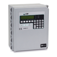
Overview of the Weigh II system, its capabilities, and components.
Details on modular PCBs, expansion options, and Kistler-Morse system flexibility.
Explanation of the Sentry™ feature for reducing vibration effects on weight readings.
Describes the two operating methods and manual notation conventions like WARNING, CAUTION, and Note.
General installation instructions, safety warnings, and prerequisites for installation.
Procedure for carefully removing and inspecting the Weigh II for shipping damage.
Instructions for wiring power and optional PCBs, detailing AC/DC differences and wire routing.
Overview of the chapter's content, including the Main Menu and keyboard functions.
Explanation of the Weigh II's menu tree structure for navigation and function access.
Explanation of specific key functions like Auto/Man, Menu, Esc, Function keys, and Alphanumeric keys.
Steps for a quick start on using the Weigh II, including initial setup and calibration.
Introduction to the Display Menu and its twelve submenus for configuring display parameters.
Setting display averaging, count increments, and units of measure for channels.
Assigning channel IDs and setting numerical display formats for readings.
Adjusting display contrast, brightness, setting time, and zero clamp for readings.
Overview of the I/O Menu, covering setpoints, current outputs, serial, printer, and PLC settings.
Setting up, adding, deleting, and configuring setpoints for vessel monitoring and control.
Setting up current outputs for transmitting weight data, including modes and fail-safe conditions.
Configuring serial communication settings like baud rate, address, and mode for external equipment.
Overview of the Calibration Menu, covering Auto, Manual, and Linear calibration types.
Performing calibration automatically by adding or subtracting material or high-accuracy methods.
Calculating and inputting scale factor weight and counts directly for calibration.
Using a linearization table to correct non-linear sensor responses for accurate readings.
Overview of the Service Menu for user-defined access codes and troubleshooting functions.
Displaying A/D counts, enabling/disabling channels, and adjusting parameters like excitation and resolution.
Implementing zero and material tracking to compensate for sensor drift and preserve accuracy.
Functions for clearing IDs, testing keyboard, printing setup, and testing/resetting NVRAM.
Overview of using math channels to perform calculations on vessel monitoring results.
Details on character limits, constants, spaces, and equation structure rules for the Weigh II.
Procedures for enabling math channels and creating equations for calculations like averaging.
Specifications for the display, data entry, memory, and serial communications.
Information on input/output cards, PLC interfaces, and electrical power requirements.
Summary of keyboard shortcuts for switching modes, scrolling, taring, and viewing information.
Lists serial commands, their functions, and expected transmitted/received data formats.
Details on how to calculate the checksum for serial commands to ensure data integrity.
Summary of Kistler-Morse's warranty for equipment defects in material and workmanship.
Information on Kistler-Morse's field service capabilities, including phone support and on-site assistance.
Lists the available technical drawings, including enclosure dimensions, interconnect diagrams, and wiring diagrams.
Procedure for pre-calibration, including obtaining A/D sensitivity and calculating parameters based on sensor type.
Using recorded material weights to refine the calibration slope and zero point.
Descriptions and solutions for ambiguous errors related to Lo Span and Hi Span values during calibration.
Explanations and solutions for ADC overrange, gross/net unit overruns, and math channel errors.
| Operating Temperature | -10°C to 50°C |
|---|---|
| Excitation Voltage | 10 VDC |
| Input Signal | mV/V from load cells |
| Output Signal | 4-20 mA, 0-10 VDC |
| Power Requirements | 115/230 VAC |
| Display | LCD |
| Enclosure | NEMA 4X |