EasyManua.ls Logo

KITA KP50 Series - User Manual

KITA KP50 Series
5 pages
Print Icon
To Next Page IconTo Next Page
Loading...
PR-0325D 2017/12 Online Version We reserve the right to change the specification without prior notice.
KITA SENSOR TECH. CO., LTD.
www.kita.com.tw
3 MPa 300 kPa
Rated pressure range
Setting pressure range
Withstand pressure
Fluid
Power supply voltage
Current consumption
Temperature characteristic
Port size
Lead wire
Weight
-0.100 ~ 2.00MPa
0.000 ~ 2.00MPa
10.0 ~ -101.3kPa
0.0 ~ -101.3kPa
-101.0 ~ 101.0kPa
-100.0 ~ 100.0kPa
-0.100 ~ 1.000MPa
0.000 ~ 1.000MPa
kPa
kgf/cm
2
bar
psi
inHg
Set pressure
resolution
0.1
MPa
0.001
0.01
0.01
0.1
0.1
0.001
0.001
0.01
Non-corrosive fluid SUS 316L
Sealed liquid Silicon oil
12 to 24V DC ±10%, Ripple (P-P) 10% or less
±0.3% F.S. ±1 digit
IP65
±3% F.S. of detected pressure (25°C) at temp. Range of 0~50°C
Oil-resistance cable(0.15mm
2
)
A. SPECIFICATIONS
0 ~ 50°C
Approx. 110g (Rear ported) ; Approx. 145g (Bottom ported)
(Positive)
Repeatability (Switch output)
Environment
F1:R1/4", M5 ; F2:NPT1/4", #10-32 UNF ; F3: G1/4"(BSPP), M5
F1C:Rc1/8"
KP50P- -
(High)
KP50H- -
(Vacuum)
KP50V- -
(Compound)
KP50C- -
Output type
Max. load current
Max. supply voltage
Residual voltage
Response time
Output short circuit protection
Yes
40mA (With no load)
1
2
3
4
5
6
7
8
Do not use corrosive fluid SUS316L, please confirm the specification in detailed.
Please use within the rating pressure range. Do not apply pressure beyond recommended maximum withstand pressure,
permanent damage to the pressure sensor may occur.
Do not drop, hit or allow excessive shock. Even if switch body appears undamaged, internal components may be broken and
can cause malfunction.
Turn power off before connecting wiring. Wrong wiring or short circuit will damage and/or cause malfunction.
This product is not explosion-proof rated. Do not use in atmosphere containing flammable or explosive gases.
Wiring for pressure sensor should avoid power source line and high voltage line. If use in the same circuit, noise may cause
malfunction.
The product is complied CE certificate, but no surge absorber. If required, please find other way to solve.
Do not exceed the screw-in torque of 13.6 N.m when installing piping. Exceeding this value may cause malfunction.
2 NPN or 2 PNP open collector
125 mA
1.5V
30V DC (at NPN output), 24V DC (at PNP output)
Switch
output
LCD display
Switch ON Indicator
Updates time
Indicator accuracy
Enclosure
Operation ambient temp. range
Storage ambient temp. range
Ambient humidity range
Withstand voltage
Insulation resistance
Vibration
Shock
Orange (1 & 2 Indicator) OUT1 OUT2
± 2% F.S. ± 1 digit (ambient temperature: 25 ±C)
About 0.2s
Display
2.5ms (chattering-proof function: 25ms, 100ms, 250ms, 500ms, 1000ms and 1500ms selections)
Voltage
output
Current
output
Voltage
Impedance
Current
Impedance
Linearity ±1% F.S.
4~20mA ( ± 2.5%)
Analog
output
35 ~ 85% RH (No condensation)
-10 ~ 60°C (No condensation or freezing)
250V AC in 1-min (between case and lead wire)
50 (at 500V DC, between case and lead wire)
Total amplitude 1.5mm or 10G,10Hz-55Hz-10Hz scan for 1 minute, two hours each direction of X, Y and Z
100m/s
2
(10G), 3 times each in direction of X, Y and Z
KP50
Series
0.001(~1.999)
0.01(2.00~)
0.01(~19.99)
0.1(20.0~)
0.01(~19.99)
0.1(20.0~)
0.1(~199.9)
1(200~)
For your safety, please read the following before using.
1~5V ( ± 2.5% F.S.)
Max.Load Impedance: 250Ω at power supply of 12V
600Ω at power supply of 24V
Min.Load Impedance: 50Ω
About 1kΩ
digit, 7segment (red/ green)
All manuals and user guides at all-guides.com
all-guides.com
Question and Answer IconNeed help?

Do you have a question about the KITA KP50 Series and is the answer not in the manual?

Summary

Important Safety Precautions

Corrosive Fluid Usage Warning

Do not use corrosive fluid SUS316L; confirm specification before use.

Pressure Range Adherence

Use within the rating pressure range to prevent permanent damage.

Shock and Impact Avoidance

Avoid dropping or shock, as internal components can be damaged.

Electrical Wiring Safety

Turn off power before wiring; wrong wiring can cause malfunction.

Hazardous Atmosphere Restriction

Do not use in atmospheres containing flammable or explosive gases.

Noise Interference Prevention

Wire pressure sensor away from power/high voltage lines to prevent noise.

Surge Protection Consideration

CE compliant, but no surge absorber; consider alternative solutions.

Screw-in Torque Limitation

Do not exceed 13.6 N.m screw-in torque for piping installation.

KP50 Specifications Overview

Pressure Range Specifications

Details rated and setting pressure ranges for different models.

Fluid and Sealed Liquid Compatibility

Specifies compatible fluids and sealed liquid types.

Resolution and Measurement Units

Defines set pressure resolution in various units (kPa, MPa, etc.).

Power Supply and Current Consumption

Details required voltage, current draw, and maximum load.

Switch Output Characteristics

Describes output type, load current, response time, and protection.

Analog Output Details

Specifies voltage and current output ranges and impedance.

Display and Indicator Features

Information on LCD display, indicators, and accuracy.

Environmental Operating Conditions

Details ambient temperature, humidity, vibration, and shock resistance.

Electrical Ratings and Resistance

Specifies withstand voltage and insulation resistance.

Temperature and Port Specifications

Covers temperature characteristics, port size, and lead wire.

Ordering and Panel Information

Ordering Code Structure

Guide to selecting pressure range, output, and port options.

Optional Parts Identification

Codes for optional accessories like mounting brackets and adapters.

Panel Description and Indicators

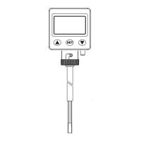
Overview of the panel layout, display, and indicators.

Output Circuit Wiring Diagrams

Illustrates wiring connections for different output types.

Dimensional Drawings

Provides physical dimensions and mounting details.

Optional Parts Dimensions

Dimensions for mounting brackets and panel adapters.

Setting Modes and Functions

Initial Setting Mode Operations

Guide for setting output operating mode, type, and response time.

Display Color and Unit Settings

Instructions for changing display color and pressure units.

Advance Setting Mode Functions

Covers hysteresis value, display color, power-save, and copy function.

Restore Factory Settings

Procedure to reset the sensor to its default factory configuration.

Advanced Operational Modes

Power-Save Mode Operation

Details on display dimming and temporary display activation.

Output Type 1 Settings

Configuration for one-point, hysteresis, and window comparator modes.

Pressure Setting Mode Guide

Instructions for setting one-point, hysteresis, and window values.

Analog Output Signal Description

Explains analog output ranges (1-5V, 4-20mA) relative to pressure.

Zero Point Calibration

Procedure to set the zero point for accurate pressure readings.

Advanced Functions and Troubleshooting

Max;Min Display Mode

How to view and reset the maximum and minimum displayed values.

Key Lock;Unlock Mode

Procedure to lock or unlock the sensor's control buttons.

Copy Function for Sensor Settings

Steps to copy settings from a master sensor to a slave sensor.

Wire Installation Instructions

Guidance on correctly installing the sensor's wiring.

Error Code Interpretation

Explanation of error codes and their troubleshooting.

Pressure Unit Conversion Table

Table for converting between different pressure units.

KITA KP50 Series Specifications

General IconGeneral
BrandKITA
ModelKP50 Series
CategorySwitch
LanguageEnglish