IMPORTANT: Read completely before installing to save time, work,
assure proper performance, and owner’s warranty protection.
ELECTRICAL SPECIFICATIONS
;Eg;;; (KECS1040), EN-300
KECS160
KECX160
E!SU-360
;E;;,f!j (KECG-2640), ESUG-360
Voltage
and
Frequency
240 volts or 208 volts,
Voltage and Frequency
240
volts or 208 volts,
60 hertz
60 hertz
Operating Load
30 amperes
Operating Load
375 amperes max.
Maximum Protective
Maximum Protective
Device Size 40 amperes
Device Size
50 amperes
Minimum Circuit Size
40 amperes
Minimum Circuit Size
50 amperes
WARNING: ELECTRICAL AND GROUNDING CONNECTIONS MUST COMPLY WITH APPLICABLE PORTIONS OF
THE NATIONAL ELECTRICAL CODE AND/OR OTHER LOCAL ELECTRICAL CODES.
The bare copper wire in factory installed conduit is the unit ground wire, not a neutral conductor.
INSTALLATION INSTRUCTIONS
All work should be done by a qualified electrician who is familiar with the National Electrical Code and/or Local Codes.
WARNING: DISCONNECT ELECTRICAL POWER SUPPLY AND PLACE A TAG AT THE DISCONNECT SWITCH IN-
DICATING THAT YOU ARE WORKING ON THE CIRCUIT
FOR REPLACEMENT COOKTOP INSTALLATION INSTRUCTIONS
GO To SECTION E OF THIS BOOKLET
NEW INSTALLATION
THE FOLLOWING INSTRUCTIONS ARE FOR NEW INSTALLATIONS ONLY.
Before installing unit be sure that the electrical supply meets the electrical specifications given in this booklet for your model.
SECTION A
- ELECTRICAL SUPPLY
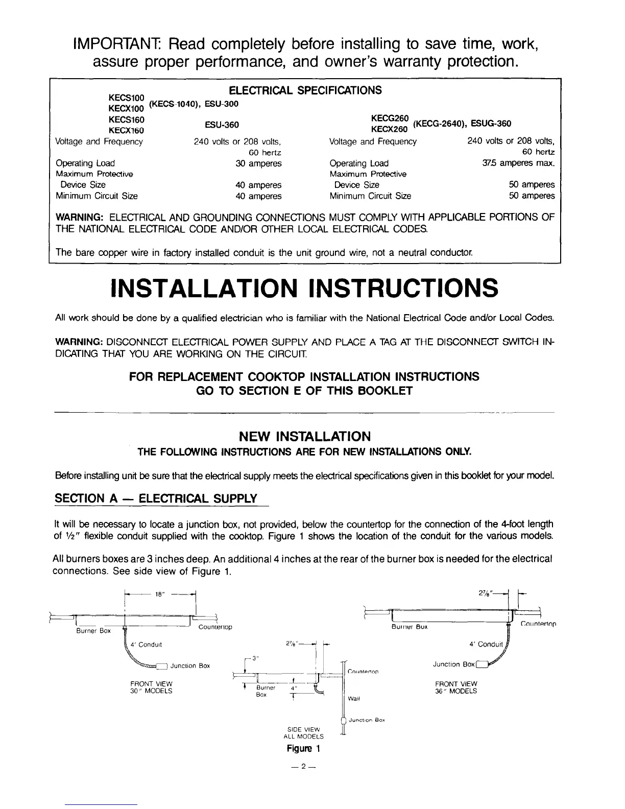
It will be necessary to locate a junction box, not provided, below the countertop for the connection of the Cfoot length
of l/z” flexible conduit supplied with the cooktop. Figure 1 shows the location of the conduit for the various models.
All burners boxes are 3 inches deep. An additional 4 inches at the rear of the burner box is needed for the electrical
connections. See side view of Figure 1.
Burner Box
JuncUon Box
FRONT VIEW
30” MODELS
FRONT VIEW
36” MODELS
i
Juncl~on Box
SIDE VIEW
ALL MODELS
Figure 1
-2-