Instruction Manual ES 50 plus page 6
___________________________________________________________________________________________________________________
Instruction Manual
for the electric-hydraulic cutting unit Type ES 50 Plus,
Serial-No. ............................
Index
1 Introduction
2 Labels
3 Warranty
4 Description of the electric-hydraulic cutting unit
4.1 Description of the components
4.2 Brief description of the important features of the unit
4.3 Description of the light diode display
5 Remarks in respect of the determined use
5.1 Operation of the units
5.2 Explanation of the application range
5.3 Service and Maintenance instructions
5.4 Remarks on the use of the Battery Cartridge and Charger
5.5 Storage and transport of the cutting unit.
6 Troubleshooting
7 Putting out of operation/waste disposal
8 Technical data
Symbols
Safety warnings
Please do not disregard these instructions in order
to avoid human injuries and environmental
damages.
Operational warnings
Please do not disregard them to avoid damaging the
pump unit.
1. Introduction
Before starting to use the tool please read the
instruction manual carefully.
Use this tool exclusively for its determined use.
Mounting and assembly of connecting material with the help of
this tool must only be performed by specially trained personnel.
The minimum age is 16 years.
This instruction manual has to be carried along during the entire
life span of that tool.
The operator has
- to guaranty the availability of the instruction manual for the user
and
- to make sure, that the user has read and understood the
instruction manual.
2. Labels
On the labels fixed on the housing of the tool you’ll find the type
specification name of the manufacturer and the company logo. On
the opposite side of the housing you’ll find a label with a brief
presentation of the scope of manageable cross-sections for copper
and aluminium and the cutting force. The serial number is on the
hydraulic cylinder between the housing and the cutting head. On
the cutting head you’ll find a warning against possible injuries
during the cutting process.
3. Warranty
If correct operation is guaranteed our warranty is 6 months from
the time of delivery unless otherwise specified by local guidelines
and law.
4. Description of the electric-hydraulic cutting unit
4.1. Description of the components
The electric-hydraulic cutting unit type ES 50 Plus is a hand held
tool and consists of the following components:
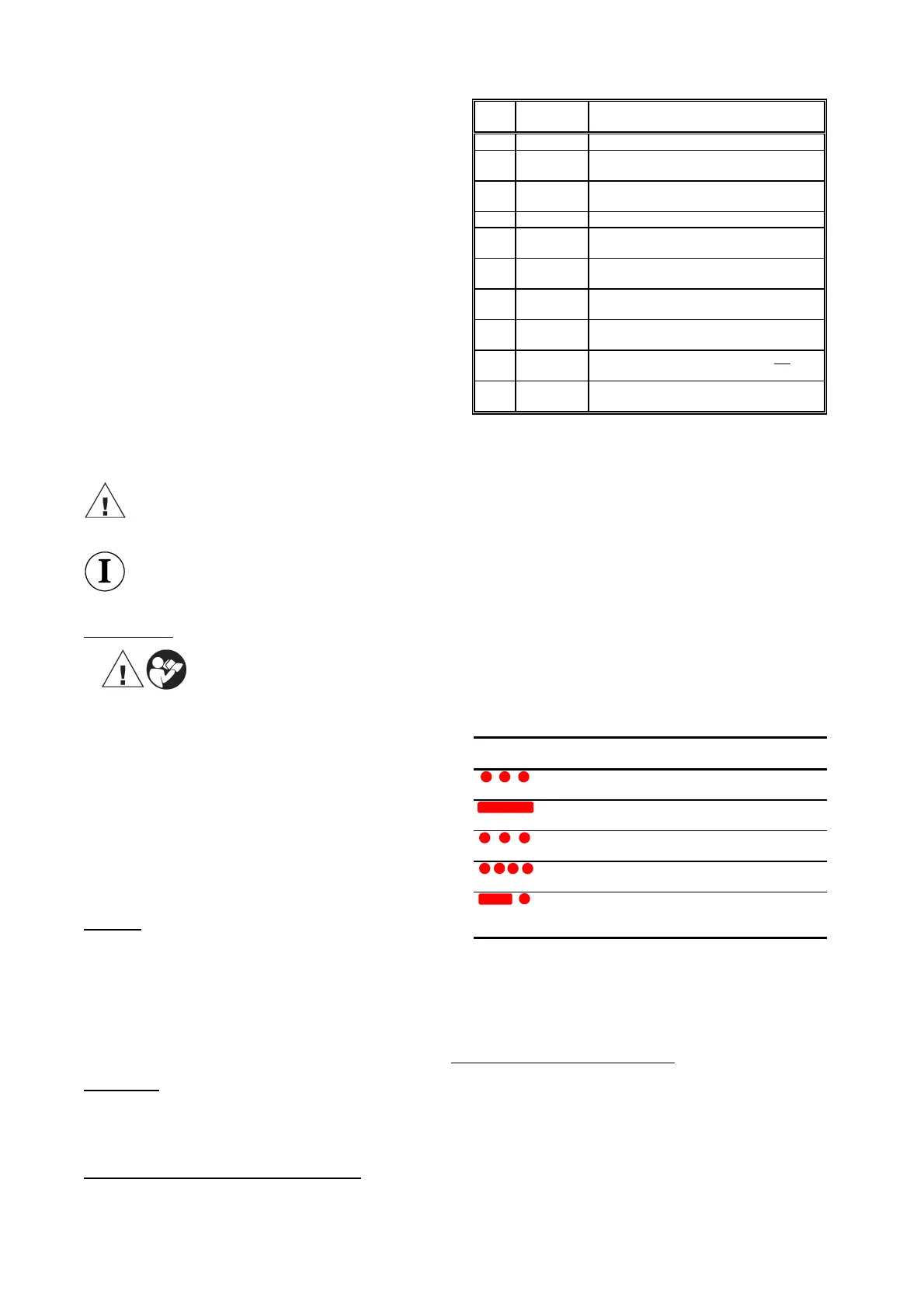
Table 1 (see Picture 1 page 2)
Pos.-
No.
Description Function
1 Trigger switch to start cutting procedure
2 Retract
button
button to open the blades in case of
emergency
3 Cutting
head
Device for the reception of the blades
4 Handle Device to guide the cutting head
5 Housing ergonomically formed plastic housing for
perfect handling with a detachable lid
6 Light diode
display
indicator for tool functions and battery
charge control
7 Battery
cartridge
rechargeable 2,6Ah NiMH battery (RA4)
8 Ring Loop to secure the tool and/or assembly
purposes
9 Removable
hand guard
guard to protect the operating hand, not for
transportation
10 Blades cutting blades for copper and aluminium
cables and connectors w/o armour & ACSR
4.2. Brief description of the important features of the unit
- The hydraulic unit incorporates a manual retraction enabling the user
to returns the piston into its starting position if necessary.
- The unit is equipped with a special brake which stops the forward
motion of the piston/blades when the trigger (Pos.-No. 1) is released.
- The unit is equipped with a double piston pump which is characterised
by a rapid approach of the blades (Pos.-No. 10) towards the cable and
a slow cutting motion.
- The cutting head can be smoothly turned by 360° around the
longitudinal axis in order to gain better access to tight corners and
other difficult working areas.
- The ES 50 Plus is equipped with a microprocessor which indicates
service intervals, internal checks and low battery charges.
4.3. Description of the light diode display
This tool is equipped with a special circuit board incorporating several
important features to inform the user about the current status of the unit.
The diode (Pos.-No. 6) signals in the following cases:
Signal Duration When it
occures
What it means
a few seconds of
flashing
battery
insertion
self check – O.K.
glowing for
20 seconds
after crimp battery discharged
1
flashing for
20 seconds (2Hz)
after crimp return for service
2
flashing for
20 seconds (5Hz)
During high
temperature
unit too hot
20 sec. glowing
and flashing
intermittently
after crimp service required
and battery flat
1
Remarks:
- Does the diode signal periodically at the end of a working cycle for
approx. 20 sec the unit must be returned to an authorised Service Center
for Service as soon as possible.
- In case of an error the light diode display also signals periodically at the
end of a working cycle. The signal indicates in this case the circuit opening
by the electronic fuse. A possible reason for that is that a cycle was
performed with an incorrectly low battery. If the signal occurs even after
changing the battery there must be a different error or a service is due. In
these cases the tool must be returned to the manufacturer or an authorised
service center.
2
The unit switches off when it gets too hot. It switches on automatically
after the unit cooled off.
 Loading...