Installation Manual
Installation
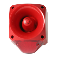
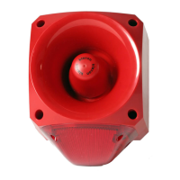
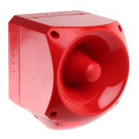
a. The sounder is installed by first mounting the base unit and making the
external wring connections to the base. The head unit then automatically
connects when it is attached to the base.
b. The sounder head is separated from the base by unlocking the four
¼-turn fasteners in the corners of the sounder. (Recommended
screwdriver: Philips No. 2, min 100mm long).
c. Note that the head only fits onto the base one way around.
Wiring
a. Power
Each power terminal is duplicated to enable simple ‘daisy-chain’
connection of multiple units.
b. Remote Tone Switching (If required): Externally link control terminals
as shown below.
EN
Sounder
Device Common (Neutral) 20 -50V AC
Alarm Stage Example Signal Activation
Technical Specification:
Supply Voltage Range 20-53V AC 50/60Hz
Current 10-50mA* max.
(Typ. 45mA @ 24V, Tone 1)
Peak Sound Level 104-116 dBA at 1m*
(Typ. 110dBA @ 24V, Tone 1)
Number of Tones 64
Frequency Range 340 - 2900 Hz*
Volume Control 20 dBA typical
Remote Tone Switching Provision for 3 volt-free contact
activated alarm stages
Operating Temperature - 25°C to +55°C
Casing High Impact Polycarbonate/ABS
IP Rating IP66 with suitable cable glands
Synchronisation Automatic with Klaxon Nexus and
Sonos Sounders
*depends on selected tone and supply voltage
The European directive “Waste Electrical and Electronic Equipment” (WEEE)
aims to minimise the impact of electrical and electronic equipment waste on
the environment and human health. To conform with this directive, electrical
equipment marked with this symbol must not be disposed of in European public
disposal systems. European users of electrical equipment must now return
end-of-life equipment for disposal. Further information can be found on the
following website: http://www.recyclethis.info/.
Low Voltage AC Sounder
Installation Instructions
AC1
AC2
S2
S
3
Stage 1 ‘Alert’ No Connection (Default)
Stage 2 ‘Evacuate’ Link Terminal to terminal
Stage 3 ‘All Clear’ Link Terminal to terminal
Controls
a. Tone Selection
The first and second stage alarm tones are independently set using
6-way dipswitches S1 and S2 respectively. The required settings are
shown in the table overleaf. The third stage alarm tone is pre-set to
complement the selected first stage tone as shown in the table.
b. Volume Control
The sound output of the unit can be reduced by up to 20dBA by
adjusting the potentiometer. At low sound levels the sound may take
a few seconds to decay away after power is removed from the
sounder.
 Loading...