ENGLISH
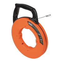
The main function of the 50611 Magnetic Wire Puller is
for pulling wires and/or cables within wall cavities. The
50611 Magnetic Wire Puller will work in walls both with
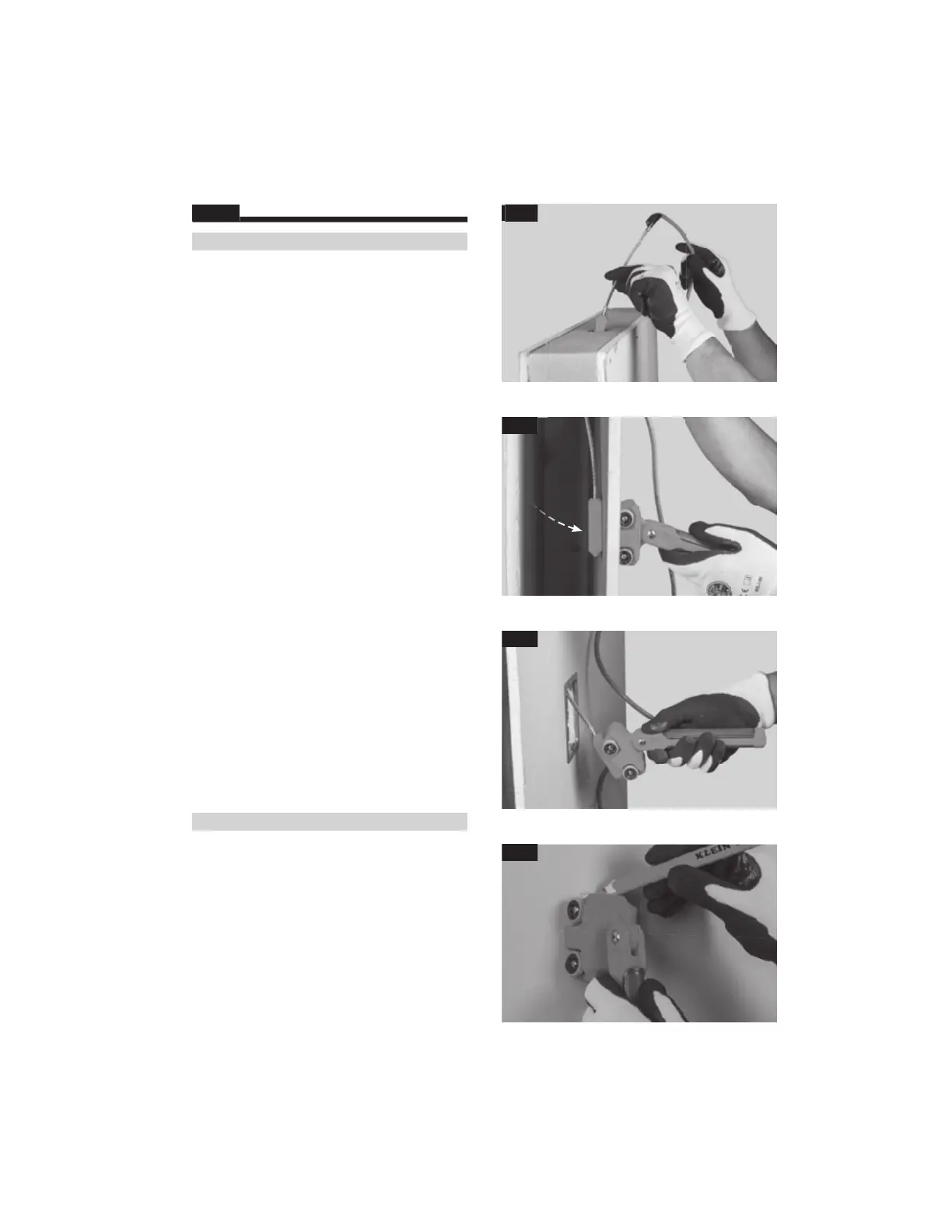
Tie off wire(s) or cable(s) to be ran behind the wall to
the Eye-loop Tip, using a polyester pull string if needed.
Drill a Ø7/8” hole in wall top plate, or other wire feed
location, for the leader unit to be inserted into. It is
important to drill in the center of the wall cavity, and
nearest to the drywall as possible (FIG. B).
If pulling wires in a wall with insulation, it is important
to get the Leader Unit in between the insulation and
With the Leader Unit in the wall cavity, use the Handheld
Unit’s Magnetic Base to locate the Leader Unit through
the drywall. The Handheld Unit and Leader Unit will
magnetically attach through the wall (FIG. C).
With the two units magnetically connected, slowly pull
the Handheld Unit towards the wall cutout location,
while also using light force to push the Handheld Unit
When approaching the wall cutout, carefully pull the
Handheld Unit until the Leader Unit pulls through the
cutout and attaches to the Handheld Unit. Slowly pull
the Leader Unit and wire(s)/cable(s) through the wall
The 50611 Magnetic Wire Puller can also be used in
other wire and cable pulling applications. These may
include, but not be limited to, pulling across ceilings,
raised floors, under carpet, etc.
The 50611 Magnetic Wire Puller also works as a stud
finder, for both metal and wood studs. For this use,
roll the Handheld Unit slowly across a wall until it
magnetically attaches to a metal stud, or a nail in a
wood stud. Then, align the Handheld unit vertically
or horizontally and, using a pencil, use one of the four
V-notches in the Magnetic Base to mark the center of
FIG. B
FIG. C
FIG. D
FIG. E
www.GlobalTestSupply.com
Find Quality Products Online at: sales@GlobalTestSupply.com
 Loading...