1
GENERAL VIEW & DEFINITIONS / VISTA GENERAL Y DEFINICIONES
Device model (Modelo de dispositivo) DPR 3110 DPR 3120 DPR 3111 DPR 3121 DPR 3110E DPR 3120E
Order Number (Número de pedido)
270 600 270 601 270 602 270 603 270 604 270 605
Connection (Montaje) Rail mount (Montaje en riel) Rail mount(Montaje en riel) Rail mount(Montaje en riel)Rail mount(Montaje en riel) Rail mount(Montaje en riel) Rail mount(Montaje en riel)
Basic measurements (Mediciones básicas)
LCD
Alarm definition (Identificación de alarma)
Neutral connection (Conexión Neutral)
- -
PTC error (Alarma PTC)
-
-
-
Relays (Cantidad de Relés)
1 2 1 2 1 2
External Supply (Fuente externa)
- - - -
• Over voltage
• Under voltage
• Over Frequency
•Sobre-voltajes
•Sub-voltajes
•Sobre-frecuencias
• Under Frequency
• Asymmetry
• Sequence
•Sub-frecuencias
•Asimetría
•Secuencias
• Phase loss
• PTC error
•Pérdidas de fase
•Error PTC
CARACTERÍSTICAS GENERALES
DPR 31xx es una serie de relés digitales de protección y monitoreo
diseñados para sistemas trifásicos, medición de voltaje, frecuencia y
monitorea los siguientes parámetros:
BOTONES Y SUS FUNCIONES
Los botones validos en el panel frontal y sus funciones se describen en la siguiente tabla.
GENERAL FEATURES
DPR 31xx series is a digital protection and monitoring relay designed for three-phase
systems, measures voltage, frequency and monitors
these parameters below:
BUTTONS & THEIR FUNCTIONS
The buttons valid on the front panel and their functions are described on the following table:
PROPER USE AND SAFETY CONDITIONS
• Installation and connections should be established in accordance with the instructions
set out in the manual by authorized persons. Unless the connection is built properly,
device should not be operated.
• Before wiring the device up, make sure that energy is cut off
• Use a dry cloth to remove the dust from the device/clean the device. Avoid using
alcohol, thinner or a corrosive material.
• Device should be engaged only after all the connections are made.
• Do not open the inside of the device. There are no parts which the users can intervene inside.
• Device should be kept away from humid, wet, vibrant and dusty environments.
• It is recommended to connect a breaker or automatic fuse (2 amper) between the
voltage inputs of the device and the network.
The manufacturing company may not be kept responsible for unfavorable
incidents that arise out of the failure to follow the above cautions.
When any of the alarms is active, the background light will blink as long as the
alarm is active. However, if the “latch on” option is active and the alarm is assigned to any
relay output, the alarm icon will appear on the display and the relay output will be active
when an error occurs. Even if the alarm is inactive, the “latch on” option is active, so the
relay will remain active and background light will continue to flash until the device is reset.
USO ADECUADO Y CONDICIONES DE SEGURIDAD
La compañía fabricante no se hace responsable por incidentes
desafortunados que son resultado de no seguir las precauciones anteriores.
Cuando alguna de las alarmas se active, la luz de fondo parpadeará
mientras la alarma siga activa. Sin importar que la opción “Latch On” esté
activada y la alarma esté asignada a un relé de salida, el icono de alarma
aparecerá en la pantalla y el relé de alarma se activará cuando un error ocurra.
Incluso si la alarma está inactive, la opción “Latch On” será activada, así el relé
permanecerá activo y la luz de fondo continuará parpadeando hasta que el
dispositivo se reinicie.
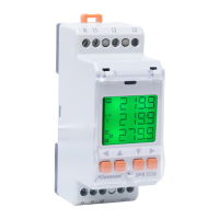
ICONS & LEDS
Descriptions of icons that appear on the screen, shown in the figure below.
ICONOS Y LEDS
Las descripciones de los iconos en la pantalla se muestran a continuación.
Activated at the history screen (Pantalla de memoria activada)
Activated when Relay-1 is active (Relé 1 activado.)
Activated when Relay-2 is active (Relé 2 activado.)
Activated to show phase to phase voltage (Muestra voltaje fase-fase.)
Activated to show phase to neutral voltage (Muestra voltaje fase-neutro.)
Unit of voltage (Unidad de voltaje.)
Unit of frequency (Unidad de frecuencia.)
Activated when over voltage error occurs (Error de sobre-voltaje.)
Activated when sequence error occurs (Error de secuencia.)
Activated when frequency error occurs (Error de frecuencia.)
Activated when PTC error occurs (Error de PTC.)
Activated when asymmetry error occurs (Error de asimetría.)
Activated when under voltage error occurs (Error de sub-voltaje.)
SERIES / SERİE
DPR
(DPR 31..E) (DPR 31..)
Reset
R2
Test
SetupExit
R1
Test
• La instalación y las conexiones deben ser establecidas de acuerdo con
lasinstrucciones incluidas en el manual por personal autorizado. El dispositivo no debe
ser operado hasta que se haya conectado correctamente.
• Antes de cablear el dispositivo, asegúrese que no haya energía.
• Use un paño seco para remover el polvo del dispositivo, evite usar tinner, alcohol o
material corrosivo.
• El dispositivo debe ser encendido solamente si se han realizado las conexiones.
• NO destape
el dispositivo. No hay piezas en el interior que el usuario pueda intervenir.
• El dispositivo debe mantenerse lejos de humedad, agua, vibraciones y entornos
polvorientos.
• Se recomienda conectar un breaker o fusible automático (2A) entre las entradas de
voltajedel dispositivo y la red.
Operation Mode (Modo de operación)
- -