
L
lindsey65Aug 5, 2025
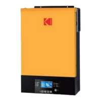
What to do if my Kodak 5KVA-220V displays a 09 fault?
- NNatalie ClarkAug 5, 2025
If your Kodak Inverter shows a 09 fault, it indicates that the DC-DC module is damaged. You can either repair the main board or replace it directly.