Do you have a question about the Kohler BEAM K-77691K-G and is the answer not in the manual?
This document provides comprehensive installation and maintenance instructions for the KOHLER BEAM Urinal Flush Valve, models K-77691K-G, K-77692K-G, and K-77693K-G. Designed for high-quality bathroom applications, this accessory ensures efficient and reliable flushing. The manual emphasizes careful reading of the instructions to ensure proper care, assembly, and long-term functionality of the product. It is crucial to retain this instruction manual for future reference, as it contains vital information for troubleshooting and maintenance.
Before commencing any installation work, particular attention must be paid to safety warnings. When drilling into walls, it is imperative to use an electronic detector to check for hidden electrical wires, communication cables, or water supply pipes. This precaution prevents accidental damage and potential hazards. If power tools are used, always wear eye protection to safeguard against debris and unplug the equipment after use to prevent accidental activation. These safety measures are fundamental to a safe and successful installation process.
The installation process begins with preparing the wall. The first step involves drawing lines and drilling the wall according to the provided diagram (Fig. 2). For optimal placement, the horizontal distance between the bottom of the mounting plate and the top surface of the urinal is recommended to be 230mm. The depth of the installation can be adjusted as desired by the customer to suit specific requirements. This flexibility allows for customization based on the bathroom layout and user preferences.
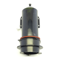
Once the wall is prepared, the next step is to fix the box. The box should be inserted into the prepared opening in the wall as shown in Fig. 3. After adjusting its position, secure the box firmly with four screws. Following this, the inlet and outlet pipes need to be cut according to the marked lines on the box. The inlet pipe requires a G1/2 female thread. It is critical to ensure that the cut ends of both the inlet and outlet pipes are level, clean, and properly aligned both vertically and horizontally. This precision is essential for preventing leaks and ensuring the correct flow of water.
After the box is secured and the pipes are prepared, the excessive part of the box protruding from the wall must be cut off, as illustrated in Fig. 4. This ensures a flush and aesthetically pleasing finish once the tiles are installed.
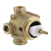
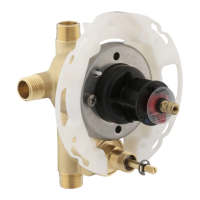
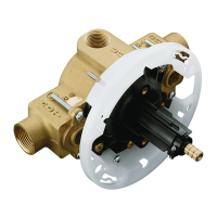
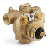
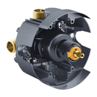
The next major step is to install the valve assembly. The valve assembly is fixed onto the inlet and outlet pipes using a wrench, as depicted in Fig. 5. For the inlet pipe, first process the inlet pipe thread and fix the inlet pipe connector. Then, place the seal onto the nut and tighten the valve assembly and inlet connector with a wrench. Before fixing the inlet pipe, it is important to clean any waste or debris from the supply pipe to prevent blockages and ensure smooth operation. For the outlet pipe, place the nut and seal onto the outlet pipe, then tighten the valve assembly and outlet connector with a wrench. Proper tightening is crucial to prevent leaks and ensure a secure connection.
Once the valve assembly is in place, the wall tiles can be cut and fixed. The tiles should be cut according to the dimensions provided in Fig. 6, ensuring a precise fit around the installed components.
The final step in the installation process is to fix the bottom board. Secure the bottom board with six self-tapping screws. The rod connector needs to be cut according to the depth into the tile, specifically to a length of 17.8mm. After cutting, fix the rod connector to the valve rod. It is important not to overtighten the nut to avoid deforming or damaging the bottom board, which could compromise the stability and appearance of the installation.
After the installation is complete, a test run is essential to check the valve's functionality and identify any potential issues. During the test run, check for leakage at the inlet connector. If leakage occurs, refer to Fig. 7 to verify if the seal is properly installed, the nut is tightened, and the inlet pipe is at the correct vertical and horizontal level. Similarly, check for leakage at the outlet connector. If there is leakage, ensure the surface is smooth, the seal is not twisted, and the nut is tightened securely.
Troubleshooting is also covered in the manual. If water continues to run from the flush valve, it may indicate that the rod connector is still too long. In this case, press the rod continuously with the button to make the valve continue working, which might help in seating the components correctly. If no water or too little water runs from the valve, it suggests that the rod connector is too short. In such instances, adjustments to the rod length may be necessary. For any other problems or persistent issues, it is recommended to contact the manufacturer for assistance.
Maintenance features are also detailed. If the flush valve cannot be stopped, press the rod to check if it can be restored to its original position. This issue might be caused by waste inside the valve assembly or a blocked component. Regular checks and cleaning can prevent such problems.
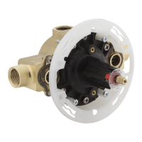
To remove the faceplate for maintenance, unscrew the top screw by 3mm, then push the faceplate upwards by 3.5mm along the wall. This allows access to the internal components for inspection or repair. When reassembling, ensure all components are correctly aligned and tightened.
In summary, this KOHLER BEAM Urinal Flush Valve manual provides a comprehensive guide from initial safety warnings and wall preparation to valve assembly, tile installation, and post-installation testing and maintenance. Adhering to these instructions will ensure the proper functioning, longevity, and aesthetic appeal of the urinal flush valve.
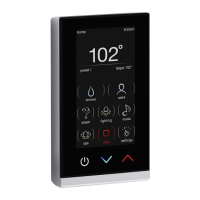
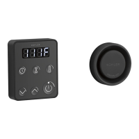
| Product Type | Control Unit |
|---|---|
| Model Number | K-77691K-G |
| Collection | BEAM |
| Brand | Kohler |
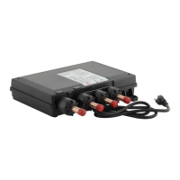
| Power | Battery-powered |
| Compatibility | Kohler Konnect products |
| Wireless Connectivity | Bluetooth |
| Mounting Type | Wall-mounted |