8.21
Section 8
Electrical System and Components
8
Figure 8-32.
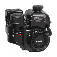
3. Plug the tester into the proper AC outlet/power
for tester being used. Turn on the power switch.
The ‘‘POWER’’ light should be illuminated and
one of the four status lights may be on as well.
See Figure 8-26. This does not represent the
condition of the part.
4. Press the ‘‘TEST’’ button until a “click” is heard
and then release. See Figure 8-27. Momentarily
either the ‘‘HIGH’’, ‘‘LOW’’, or ‘‘SHORT’’ light
will flash.
a. If the “HIGH” light flashes on/off, the part is
good and may be used.
b. If any other light is displayed* the rectifier is
faulty and should not be used.
*NOTE: A flashing “LOW” light can also occur as a
result of an inadequate ground lead
connection. Make certain connection location
is clean and clamp is secure.
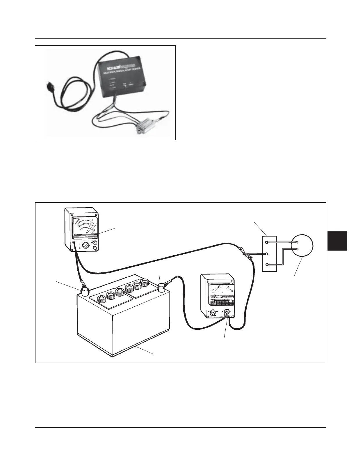
Figure 8-33. Connections for Testing Charging System.
DC Voltmeter
Rectifier-Regulator
Flywheel
Stator
Ammeter
Battery
(-)
(+)