Oil Pump Assembly (Style B)
Oil pump is mounted inside oil pan. If service is required,
continue with Disassembly, Inspection, and Reassembly.
Disassembly
1. Remove screws.
2. Lift oil pump assembly from oil pan. Remove outer
gerotor gear from oil pan.
3. Ensure ball and spring remain installed in pressure
relief hole of oil pan. If ball and spring fall out of
pressure relief hole, see reassembly for correct
installation.
4. Remove oil pump cover O-ring from groove in oil
pan.
Inspection
Inspect oil pump housing, gear, and rotors for nicks,
burrs, wear, or any visible damage. Inspect oil pump
cover O-ring for cuts, nicks, or any visible damage. If any
parts are worn or damaged, replace oil pump assembly
and/or O-ring. Check oil pickup screen for damage or
restriction, replace if necessary.
Reassembly
1. Lubricate outer gerotor gear with oil. Install outer
gerotor gear through shaft of oil pump, around inner
gerotor gear. Matching molding dots on inner and
outer gerotor gears is not necessary and will not
affect oil pump efciency.
2. Reinstall ball, then spring into pressure relief hole in
oil pan.
3. Reinstall O-ring into groove in oil pan; make sure it is
fully seated in groove.
4. Install oil pump inserting center shaft into
corresponding recess in oil pan. Apply consistent
downward pressure to oil pump cover, compressing
oil pressure relief spring and start screws. Secure oil
pump by torquing screws (in no specic sequence)
to 9.0 N·m (80 in. lb.).
5. After torquing, rotate gear and check for freedom of
movement. Make sure there is no binding. If binding
occurs, loosen screws, reposition pump, retorque
screws and recheck movement.
Remove Camshaft
Remove camshaft and shim (if used).
Inspection and Service
NOTE: To prevent repeat failures, camshaft and
crankshaft should always be replaced as a set.
Check lobes of camshaft for wear or damage. See
Specications for minimum lift tolerance. Inspect
cam gear for badly worn, chipped or missing teeth.
Replacement of camshaft will be necessary if any of
these conditions exist.
Remove Governor Cross Shaft
1. Remove hitch pin and plain washer, or retainer and
nylon washer, from governor cross shaft.
2. Remove cross shaft through inside of crankcase.
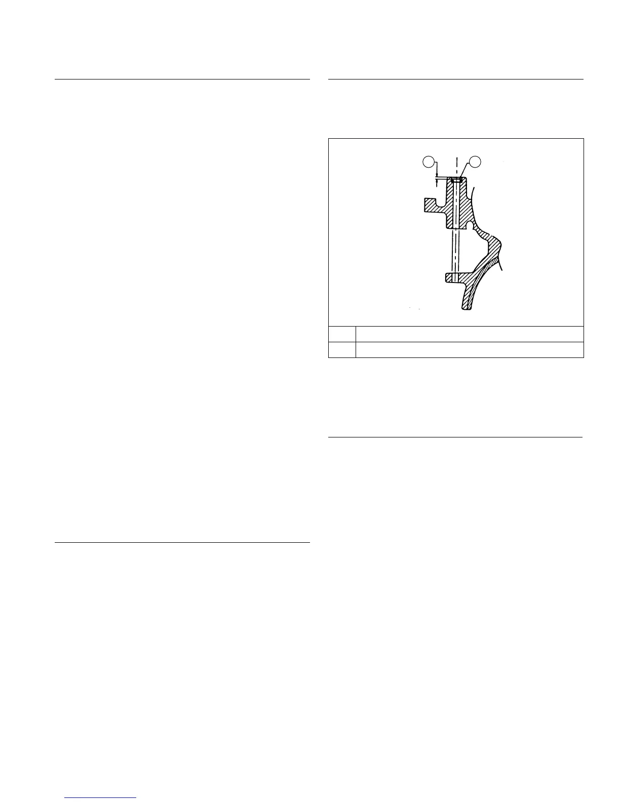
Governor Cross Shaft Oil Seal
A B
A 2.0 mm (0.0787 in.)
B Governor Cross Shaft Seal
If governor cross shaft seal is damaged and/or leaks,
replace it using following procedure.
Remove oil seal from crankcase and replace it with a
new one. Install new seal to depth shown using a seal
installer.
Remove Connecting Rods with Pistons and Rings
NOTE: If a carbon ridge is present at top of either
cylinder bore, use a ridge reamer tool to remove
it before attempting to remove piston.
NOTE: Cylinders are numbered on crankcase. Use
numbers to mark each end cap, connecting rod
and piston for reassembly. Do not mix end caps
and connecting rods.
1. Remove screws securing closest connecting rod end
cap. Remove end cap.
2. Carefully remove connecting rod and piston
assembly from cylinder bore.
3. Repeat above procedure for other connecting rod
and piston assembly.
Disassembly/Inspection and Service
6924 690 07 Rev. H KohlerEngines.com