Install Supports for Metal Debris Screen
1. If a metal debris screen is used, with threaded individual supports, install a spacer washer on external threads.
Apply blue Loctite
®
242
®
(removable) to threads. Install supports as shown.
2. Tighten supports with a torque wrench to 9.9 N·m (88 in. lb.). Debris screen will be installed to supports after
blower housing is in place.
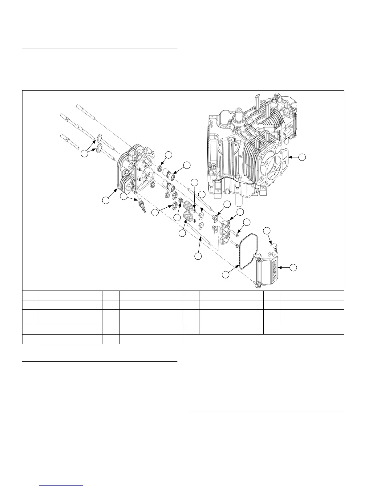
Cylinder Head Components
D
E
Q
K
L
H
B
C
G
F
A
I
J
M
N
O
P
R
A Valves B Cylinder Head C Spark Plug D Nut
E Hydraulic Lifter F Cap G Valve Stem Seal H Valve Spring Keeper
I Valve Spring J
Valve Spring
Retainer
K Rocker Arm Pivot L Push Rod
M Rocker Arm N Screw O Valve Cover O-ring P Grommet
Q Valve Cover R Gasket
Install Hydraulic Lifters
NOTE: Hydraulic lifters should always be installed in
same position as before disassembly. Exhaust
lifters are located on output shaft (oil pan) side
of engine while intake lifters are located on fan
side of engine. Cylinder numbers are embossed
on top of crankcase and each cylinder head.
1. Refer to Disassembly/Inspection and Service for
hydraulic/bleeding lifter procedures.
2. Apply camshaft lubricant to bottom surface of each
lifter. Lubricate hydraulic lifters and lifter bores in
crankcase with engine oil.
3. Note mark or tag identifying hydraulic lifters as either
intake or exhaust and cylinder 1 or cylinder 2. Install
hydraulic lifters into their appropriate locations in
crankcase. Do not use a magnet.
4. If breather reeds and stops were removed from
crankcase, reinstall them at this time and secure
with screw. Torque screw to 4.0 N·m (35 in. lb.).
Valve Stem Seals
These engines use valve stem seals on intake valves
and occasionally on exhaust valves. Use a new seal
whenever valve is removed or if seal is deteriorated or
damaged in any way. Never reuse an old seal.
Reassembly
80
24 690 07 Rev. HKohlerEngines.com