CV750 Engines
Governor Shaft
Conguration
Intended Maximum RPM With Governed Idle Systems
High Idle WOT Spring Color Hole No.
Standard
(Parent Material)
3888
3780
3672
3564
3456
3348
3600
3500
3400
3300
3200
3100
Clear
Orange
Blue
Red
Clear
Clear
3
1
1
1
1
1
Install Electric Starter Motor
1. Install starter motor using screws. Position lift
bracket to also secure dipstick tube. Some inertia-
drive starters have a pinion cover and spacers on
starter bolts.
2. Torque screws to 15.3 N·m (135 in. lb.).
3. On models with a solenoid shift starter, connect
leads to solenoid.
4. Install dipstick tube and align mounting hole with
threaded hole in lift bracket. Secure with M5 screw.
Torque screw to 4.0 N·m (35 in. lb.).
Install Fuel Pump
WARNING
Explosive Fuel can cause res and severe
burns.
Do not ll fuel tank while engine is hot or
running.
Gasoline is extremely ammable and its vapors can
explode if ignited. Store gasoline only in approved
containers, in well ventilated, unoccupied buildings,
away from sparks or ames. Spilled fuel could ignite
if it comes in contact with hot parts or sparks from
ignition. Never use gasoline as a cleaning agent.
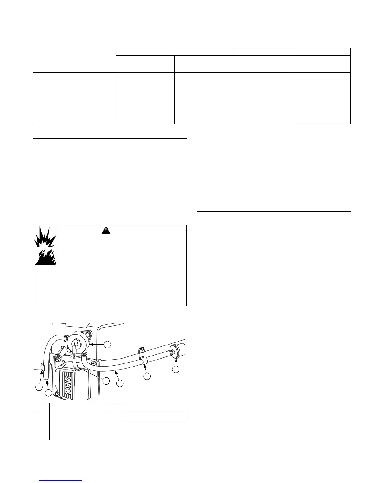
Fuel Pump Components
B
A
G
C
D
E
F
A Blower Housing Clip B Outlet Fuel Line
C Pulse Line D Inlet Fuel Line
E Fuel Line Clamp F Fuel Filter
G Fuel Pump
NOTE: Fuel pumps may be made of metal or plastic. If
a new fuel pump is being installed, make sure
orientation of new pump is consistent with
removed pump. Internal damage may occur if
installed incorrectly.
1. Install fuel pump and lines as an assembly. Connect
pulse line to crankcase vacuum tting.
2. Install fuel pump using screws. Torque screws to 2.3
N·m (20 in. lb.).
3. Connect fuel lines.
Install Air Cleaner Assembly
Low-Prole and Commercial Mower Air Cleaners
1. Connect breather hose and attach breather
separator to valve cover. Position hose in cutout of
blower housing (later models).
2. Position a new gasket and air cleaner base on studs
while carefully pulling loose end of rubber breather
hose through base until properly seated (collars
sealed against each side of base.
3. Secure air cleaner base and bracket, or spit-back
cup with bafe, using hex ange nuts. If a lower air
cleaner bracket is used, install M5 screws through
lower section of base. Torque hex ange nuts to
6.2-7.3 N·m (55-65 in. lb.), and two lower M5 screws
(when applicable) to 4.0 N·m (35 in. lb.).
4. Install air cleaner components, refer to Air Cleaner/
Intake.
Heavy-Duty Air Cleaners
1. Install a new air cleaner base gasket.
2. Attach main support bracket to four inboard valve
cover screw locations. Make sure each of mounting
holes has a loose or integral spacer. Leave screws
slightly loose.
3. Install elbow adapter onto mounting studs. Secure
with, and torque hex ange nuts to 6.2-7.3 N·m
(55-65 in. lb.).
4. Install and tighten screws securing air cleaner
mounting bracket and control panel to blower
housing.
5. Torque valve cover/mounting bracket screws to
proper specication and torque sequence listed in
Reassembly-Install Valve Covers.
6. Two-barrel carburetor models only: attach choke
return spring to bottom of main control bracket.
Reassembly
8724 690 07 Rev. H KohlerEngines.com