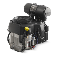
Install Breather Cover and Inner Bafe
Breather Cover Torque Sequence
1&5
2
3
4
1. Be sure sealing surfaces of crankcase and breather
cover are clean of old gasket material. Do not scrape
surfaces as this could result in leakage.
2. Check to make sure there are no nicks or burrs on
sealing surfaces.
3. Position breather gasket and cover on crankcase.
Install rst screws in locations 3 and 4 as shown.
Finger tighten at this time.
4. Install inner bafe using remaining screws and nger
tighten. Do not torque screws at this time; they will
be tightened after blower housing and outer bafes
are installed.
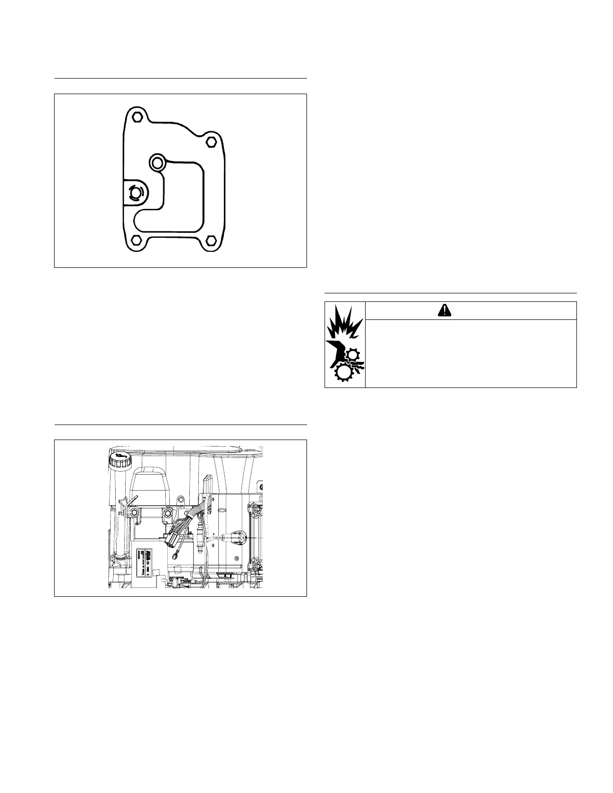
Install Blower Housing and Outer Bafes
Wires on Starter Side of Engine
367.34
[14.462]
316.96
[12.479]
40.80
[1.606]
OIL DRAIN PLUG
3/8 NPT [INCH]
12.99
[0.511]
ENGINE MOUNTING SURFACE
C
L
SPARK PLUG
72.04
[2.836]
EXHAUST
PORT #2
154.04 [6.065]
92.04
[3.624]
EXHAUST
PORT #1
STARTER SIDE
NOTE: Do not completely tighten screws until all items
are installed to allow shifting for hole alignment.
1. Pull wire harness and spark plug leads out through
appropriate openings in shrouding.
2. Slide blower housing into position over front edge of
inner bafe. Start a few of screws to hold it in place.
3. Position outer bafes and secure using screws (two
long, two short) in front mounting holes (into cylinder
head), including any lifting strap or attached
bracket(s). Install two short screws in upper
mounting holes of outer bafes (into backing plates).
Use short screw on left side to mount wire harness
bracket. Be sure any leads are routed out through
proper offsets or notches, so they will not be pinched
between blower housing and bafes.
4. Tighten all shrouding fasteners. Torque blower
housing screws to 6.2 N·m (55 in. lb.) in a new hole,
or to 4.0 N·m (35 in. lb.) in a used hole. Torque
shorter M5 side bafe screws to 4.0 N·m (35 in. lb.).
Torque M5 side bafe screws (into cylinder head) to
6.2 N·m (55 in. lb.) in a new hole, or to 4.0 N·m
(35 in. lb.) in a used hole. Torque two lower M6
bafe mounting screws to 10.7 N·m (95 in. lb.) in a
new hole, or to 7.3 N·m (65 in. lb.) in a used hole.
5. Torque four breather cover screws to 7.3 N·m
(65 in. lb.) in sequence shown.
Install Flywheel Fan and Debris Screen
CAUTION
Failure to utilize or reassemble debris screen
as designed could result in debris screen
failure and serious personal injury.
Plastic Debris Screen
NOTE: Position locating tabs on back of fan in recesses
of ywheel.
1. Install fan onto ywheel using screws.
2. Torque screws to 9.9 N·m (88 in. lb.).
3. Place plastic debris screen on fan and secure with
screws. Torque screws to 2.2 N·m (20 in. lb.).
4. Install guard and secure with screws.
Metal Debris Screen
NOTE: Position locating tabs on back of fan in recesses
of ywheel.
1. Position fan on ywheel.
2. Install a spring washer on stepped end of each
spacer with concave side down toward fan. Insert
spacers with spring washers into fan. Place support
ring on spacers. Set metal debris screen on support.
3. Install a plain washer on each screw, then apply
Loctite
®
242
®
to screw threads (M6) and insert into
screen/support ring/spacer/spring washer/fan.
Torque screws to 9.9 N·m (88 in. lb.).
4. Install guard and secure with screws.
Reassembly
6124 690 37 Rev. B KohlerEngines.com
 Loading...