Valve Guides
If a valve guide is worn beyond specifi cations, it will not guide valve in a straight line. This may result in burnt valve
faces or seats, loss of compression, and excessive oil consumption.
To check valve guide-to-valve stem clearance, thoroughly clean valve guide and, using a split-ball gauge, measure
inside diameter of guide. Then, using an outside micrometer, measure diameter of valve stem at several points on
stem where it moves in valve guide. Use largest stem diameter to calculate clearance by subtracting stem diameter
from guide diameter. If intake clearance exceeds 0.038/0.076 mm (0.0015/0.0030 in.) or exhaust clearance exceeds
0.050/0.088 mm (0.0020/0.0035 in.), determine whether valve stem or guide is responsible for excessive clearance.
Maximum (I.D.) wear on intake valve guide is 7.134 mm (0.2809 in.) while 7.159 mm (0.2819 in.) is maximum allowed
on exhaust guide. Guides are not removable but can be reamed 0.25 mm (0.010 in.) oversize. Valves with 0.25 mm
oversize stems must then be used.
If guides are within limits but valve stems are worn beyond limits, install new valves.
Valve Seat Inserts
Hardened steel alloy intake and exhaust valve seat inserts are press fi tted into cylinder head. Inserts are not
replaceable but can be reconditioned if not too badly pitted or distorted. If cracked or badly warped, cylinder head
should be replaced.
Recondition valve seat inserts following instructions provided with valve seat cutter being used. Final cut should
be made with an 89° cutter as specifi ed for valve seat angle. Cutting proper 45° valve face angle as specifi ed, and
proper valve seat angle (44.5°, half of full 89° angle), will achieve desired 0.5° (1.0° full cut) interference angle where
maximum pressure occurs on outside diameters of valve face and seat.
Lapping Valves
NOTE: Exhaust valves that are black in color cannot be ground and do not require lapping.
Reground or new valves must be lapped in, to provide proper fi t. Use a hand valve grinder with a suction cup for fi nal
lapping. Lightly coat valve face with a fi ne grade of grinding compound, then rotate valve on its seat with grinder.
Continue grinding until a smooth surface is obtained on seat and on valve face. Thoroughly clean cylinder head in
soap and hot water to remove all traces of grinding compound. After drying cylinder head, apply a light coating of SAE
10 oil to prevent rusting.
Valve Stem Seal
These engines use valve stem seals on intake and exhaust valves. Always use a new seal when valves are removed
from cylinder head. Seals should also be replaced if deteriorated or damaged in any way. Never reuse an old seal.
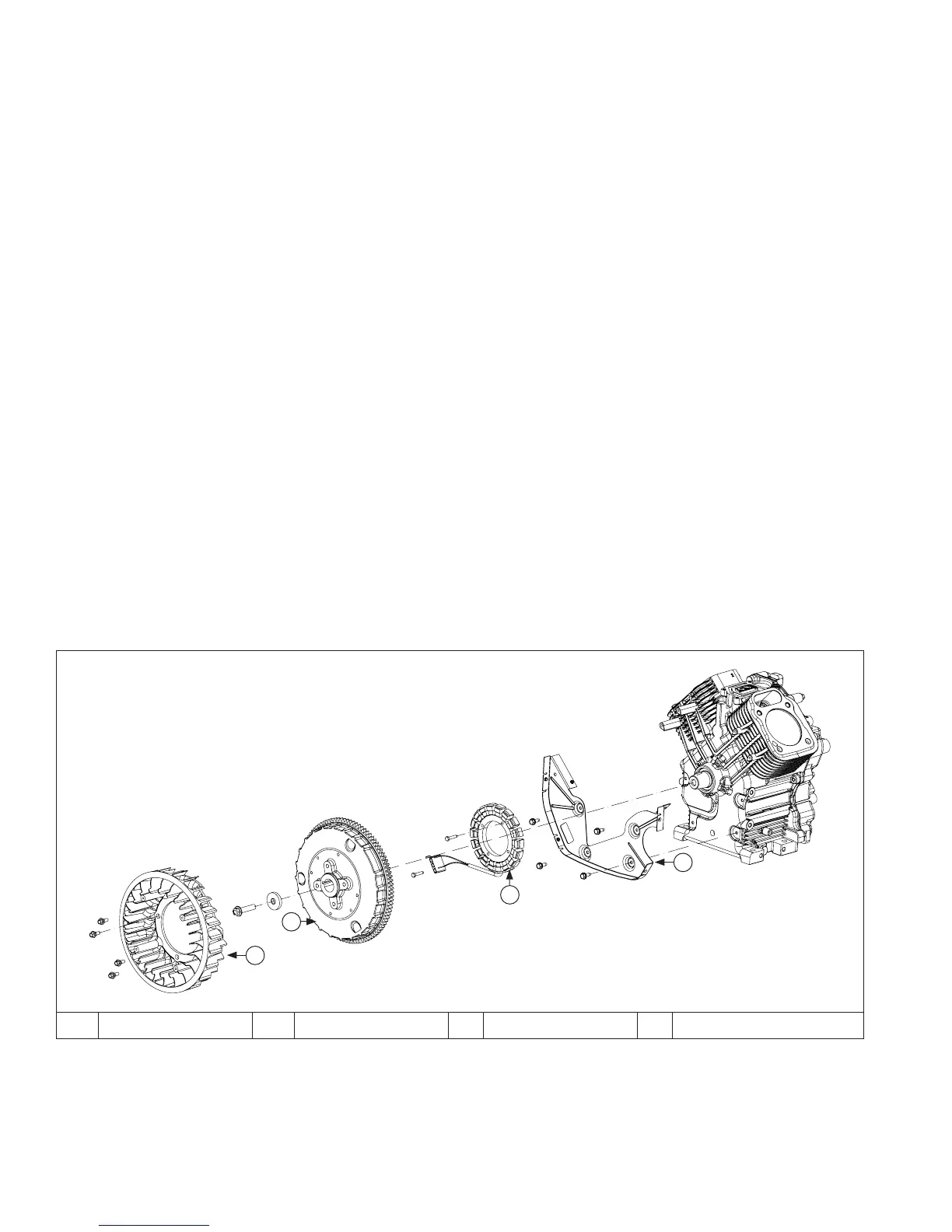
Flywheel Components
A
B
C
D
A Flywheel Fan B Flywheel C Stator D Backing Plate
NOTE: Always use a fl ywheel strap wrench or holding tool to hold fl ywheel when loosening or tightening fl ywheel
screw. Do not use any type of bar or wedge to hold fl ywheel. Use of such tools could cause fl ywheel to
become cracked or damaged.
NOTE: Always use a fl ywheel puller to remove fl ywheel from crankshaft. Do not strike crankshaft or fl ywheel, as
these parts could become cracked or damaged. Striking puller or crankshaft can cause crank gear to move,
affecting crankshaft endplay.
Disassembly/Inspection and Service
66 24 690 32 Rev. AKohlerEngines.com
 Loading...