76
Reassembly
24 690 32 Rev. AKohlerEngines.com
Oil Pump Assembly
Oil pump is mounted inside closure plate. If service was
required, and oil pump was removed, refer to assembly
procedures under Oil Pump Assembly in Disassembly/
Inspection and Service.
Governor Gear Assembly
Governor gear assembly is located inside closure plate.
If service was required, and governor was removed,
refer to assembly procedures under Disassembly/
Inspection and Service.
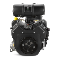
Install Closure Plate Oil Seal
Oil Seal Details
B
A
A Oil Seal B 6.5 mm (0.255 in.)
1. Check to make sure that there are no nicks or burrs
in crankshaft bore of closure plate.
2. Apply a light coat of engine oil to outside diameter of
oil seal.
3. Drive oil seal into closure plate using a seal driver.
Make sure oil seal is installed straight and true in
bore, to depth shown.
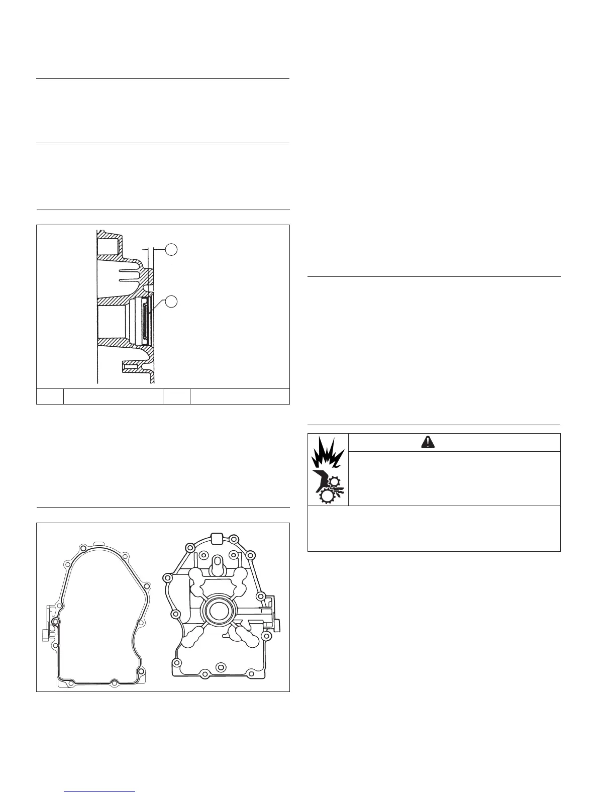
Install Closure Plate Assembly
Sealant Pattern and Torque Sequence
1
10
8
6
42
9
7
5
3
RTV sealant is used as a gasket between closure
plate and crankcase. Always use fresh sealant. Using
outdated sealant can result in leakage.
1. Be sure sealing surfaces have been cleaned and
prepared.
2. Check to make sure there are no nicks or burrs on
sealing surfaces of closure plate or crankcase.
3. Apply a 1.5 mm (1/16 in.) bead of sealant to sealing
surface of closure plate.
4. Make sure end of governor cross shaft is lying
against bottom of cylinder 1 inside crankcase.
5. Install closure plate to crankcase. Carefully seat
camshaft and crankshaft into their mating bearings.
Rotate crankshaft slightly to help engage oil pump
and governor gear meshes.
6. Install screws securing closure plate to crankcase.
Torque fasteners to 24.4 N·m (216 in. lb.) following
sequence. On some engines one mounting screw is
plated. Plated screw is typically installed in hole
location 6.
Install Stator and Backing Plate
1. Apply pipe sealant with Tefl on
®
(Loctite
®
592
™
PST
®
Thread Sealant or equivalent) to stator mounting
holes.
2. Position stator aligning mounting holes so that leads
are at bottom, towards crankcase.
3. Install and torque screws to 6.2 N·m (55 in. lb.) for
new holes or 4.0 N·m (35 in. lb.) for used holes.
4. Route stator leads in crankcase channel, then install
backing plate. Secure with screws. Torque screws
10.7 N·m (95 in. lb.) for new holes or 7.3 N·m (65 in.
lb.) for used holes.
Install Flywheel
CAUTION
Damaging Crankshaft and Flywheel Can
cause personal injury.
Using improper procedures can lead to broken
fragments. Broken fragments could be thrown from
engine. Always observe and use precautions and
procedures when installing fl ywheel.