82
Reassembly
24 690 32 Rev. AKohlerEngines.com
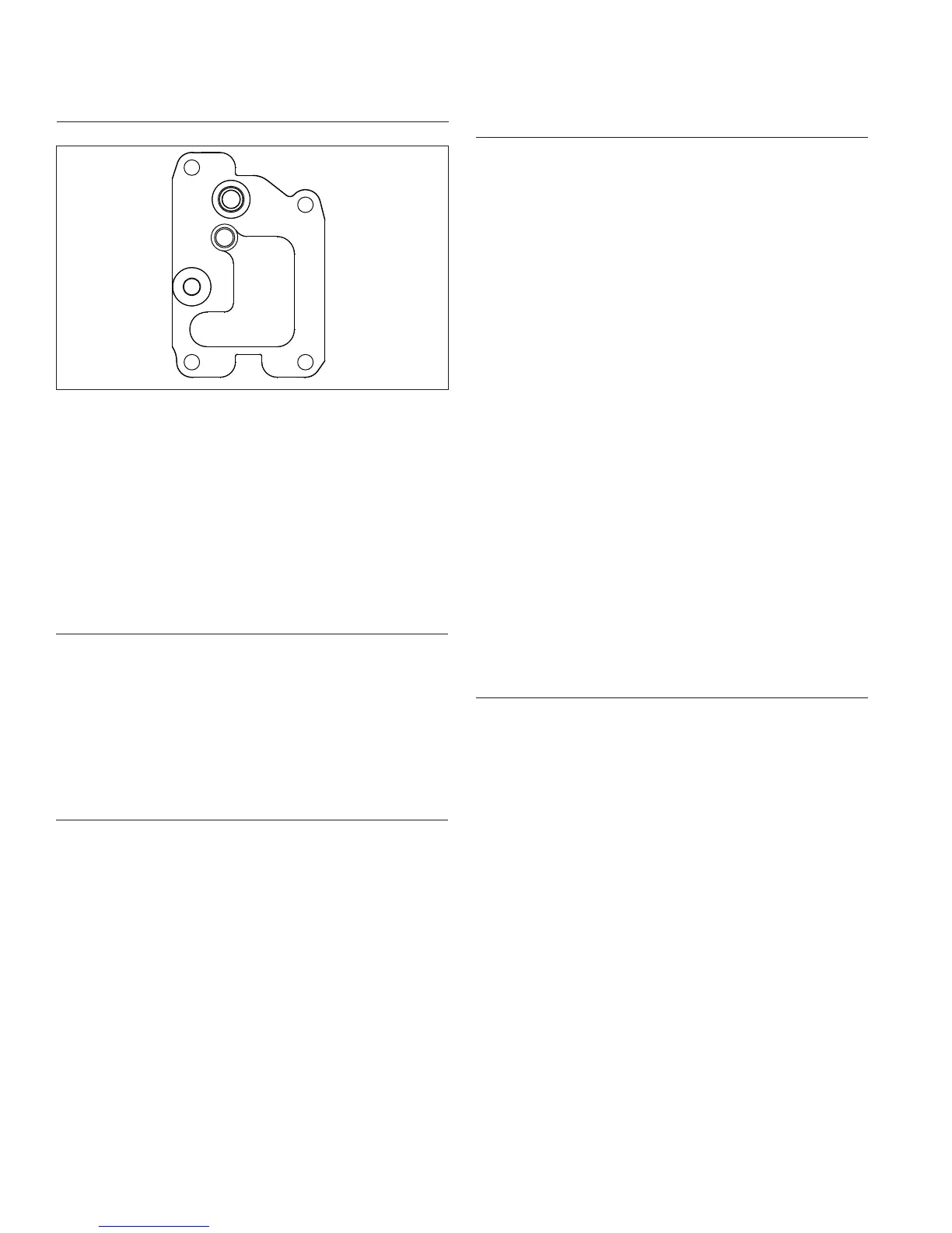
Install Breather Cover and Inner Baffl es
Torque Sequence
1&5
2
3
4
1. Be sure sealing surfaces of crankcase and breather
cover are clean of old gasket material. Do not scrape
surfaces as this could result in leakage. Use a new
gasket when installing breather cover.
2. Check to make sure there are no nicks or burrs on
sealing surfaces.
3. Position breather gasket and cover on crankcase.
Install screws in locations 3 and 4. Finger tighten at
this time.
4. Install inner baffl es using remaining screws and
fi nger tighten. Do not torque screws at this time; they
will be tightened after blower housing.
Install Oil Temperature Sensor
NOTE: Ensure part is clean, undamaged and free of
debris and make sure electrical connector has
seal in place.
1. Lightly lubricate oil temperature sensor O-ring and
install oil temperature sensor into breather cover.
2. Torque sensor to 7.3 N·m (65 in. lb.).
3. Push electrical connector on oil temperature sensor
making sure a good connection is made.
Install Oil Sentry
™
(If equipped)
1. Apply pipe sealant with Tefl on
®
(Loctite
®
592™ PST
®
Thread Sealant or equivalent) to threads of Oil
Sentry
™
switch and install it into breather cover.
Torque to 4.5 N·m (40 in. lb.).
2. Connect wire lead (green) to Oil Sentry™ terminal.
Install Blower Housing, Outer Baffl es, and Debris
Screen
NOTE: Do not completely tighten screws until all items
are installed to allow shifting for hole alignment.
1. Connect plug to key switch in blower housing (if
equipped).
2. Slide blower housing into position over front edge of
inner baffl es. Start a few screws to hold it in place.
3. Position outer baffl es and secure using M6 screws
Install M6 screws (20 mm long) into intake port side
of cylinder heads, including any lifting strap. Install
M6 screws (16 mm long) into exhaust port side of
cylinder head. Install short M5 screws (10 mm long)
in upper mounting holes of outer baffl es (into
backing plate). Be sure any leads are routed out
through proper offsets or notches, so they will not be
pinched between blower housing and baffl es.
4. Insert and tighten all remaining blower housing and
baffl e screws with exception of rectifi er-regulator
grounding bracket screw. Torque all blower housing
and baffl e M6 screws assembled into aluminum to
10.7 N·m (95 in. lb.) for a new hole, or 7.3 N·m (65
in. lb.) for a used hole. Torque all blower housing
and baffl e M5 screws assembled into sheet metal
(backing plate)to 2.8 N·m (25 in. lb.) for new holes,
or 2.3 N·m (20 in. lb.) for used holes.
5. If an overlapping style debris screen is used, attach
it to fl ywheel fan. Torque screws to 2.2 N·m
(20 in. lb.)
6. Torque breather cover screws to 11.3 N·m (100 in.
lb.) into new holes or 7.3 N·m (65 in. lb.) into used
holes in sequence shown. Note fi rst screw is torqued
a second time.
Install Reconnect Rectifi er-Regulator
NOTE: Rectifi er-regulator middle terminal (B+) is offset
(not equally spaced) from outer terminals (AC).
Verify rectifi er-regulator plug is assembled to
match terminal offset of rectifi er-regulator.
1. Install rectifi er-regulator in blower housing if
removed previously, then secure grounding bracket
against outer side of rectifi er-regulator with a silver
screw.
2. Torque black rectifi er-regulator screws to 1.4 N·m
(12.6 in. lb.) and silver ground strap screw to 2.8
N·m (25 in. lb.) into new holes or 2.3 N·m (20 in. lb.)
into used holes.
3. Connect plug to rectifi er-regulator. If purple wire was
removed, verify locking tang is raised on terminal
and push wire terminal into plug prior to connecting
to rectifi er-regulator.
 Loading...