Do you have a question about the Kohler EKOZD Series and is the answer not in the manual?
Record product identification numbers from the generator set nameplate.
Record product identification information from the engine nameplate.
Manual covers maintenance, troubleshooting, and repair of AC marine generator sets.
Provides specifications for generator set engines.
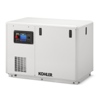
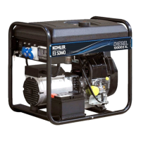
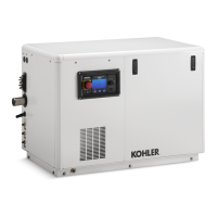
Illustrates various views of the generator set components.
Introduces specification sheets for generator set data.
Explains the concept of wound-field alternators used in specific models.
Details the concept of permanent magnet alternators for specific models.
Lists electrical values for specific alternator models.
Lists electrical values for specific alternator models.
Describes the oil pressure sender and its location.
Describes the coolant temperature sender and its location.
Describes the exhaust temperature sender and its location.
Describes the low seawater pressure switch and its location.
Details the magnetic pickup sensor and its location.
Provides torque values and specifications for alternator assembly.
Introduces controller and accessory troubleshooting information.
Identifies and lists features of the Decision-Maker® 3500 controller.
Details the Decision-Makerr 3500 controller with its integrated voltage regulator.
Lists essential checks to perform before starting the generator set.
Recommends marine vessel inspection by authorities and professionals.
Details angular limits for generator operation.
Notes compliance with EU directive for engine compartment operation.
Recommends minimum load profiles to prevent engine wet stacking.
Explains the operation of the generator set controller and its modes.
Guides routine maintenance based on service schedule and runtime hours.
Provides instructions for cleaning alternator windings.
Directs users to engine manufacturer's literature for service.
Details steps for inspecting exhaust system for leaks and blockages.
Provides instructions for servicing the mixing elbow.
Discusses fuel system setup and potential issues with dual dip tubes.
Explains the importance of fuel filter quality and replacement.
Details procedures for bleeding air from the fuel system.
Describes the components of the heat exchanger cooling system.
Explains the function of the water-cooled exhaust manifold and thermostat location.
Provides steps for coolant replacement and heat exchanger service.
Details how to check and fill the engine coolant level.
Provides procedures for flushing and cleaning the cooling system.
Discusses the function and replacement of the pressure cap.
Outlines procedures for inspecting and replacing the seawater pump impeller.
Covers checking and adjusting belt tension.
Explains the function and replacement of the anticorrosion zinc anode.
Provides procedures for inspecting the siphon break.
Introduces troubleshooting, diagnostics, and repair information for the generator set.
Lists common problems to check first before replacing parts.
Provides charts to diagnose and correct common problems.
Groups generator set faults, probable causes, and recommended actions.
Helps troubleshoot issues related to the controller display and voltage regulator.
Addresses troubleshooting steps when the breaker fails to close to the bus.
Provides troubleshooting steps when the breaker closes to the bus.
Offers troubleshooting guidance for paralleling when the system is in AUTO mode.
Details troubleshooting steps for various protective relays.
Guides troubleshooting for voltage regulator issues.
Provides troubleshooting steps for genset controller issues.
Covers troubleshooting for paralleling system issues.
Provides information on controller repair and service part replacement.
Lists necessary PC requirements for using SiteTecht software.
Explains display messages requiring user input or processing time.
Identifies inputs dependent on engine types and controls.
Outlines controller operation and summarizes button functions.
Details the controller service replacement kit and its installation.
Explains the process of matching generator output to the paralleling bus.
Provides guidelines for handling the controller to prevent damage.
Lists precautions for handling the controller and its components.
Covers the generic procedure for removal and installation of service parts.
Guides the user to parts catalogs for replacement and service kits.
Provides guidance on repairing or replacing wiring.
Details the procedure for disconnecting and removing the 24- to 12-volt converter.
Describes the function of crank relays and provides test procedures.
Explains the function and application of current transformers.
Guides testing of engine sensors installed by the manufacturer.
Explains how to test engine sensors and where to find specifications.
Lists typical controller inputs provided by sensors.
Provides procedures for testing pressure and temperature switches.
Details how to test pressure and temperature senders.
Guides testing of the oil pressure sender.
Provides instructions for testing the coolant temperature sender.
Outlines the procedure to power up the ECU for troubleshooting or reprogramming.
Explains how to test engine sensor/switch faults.
Provides information on troubleshooting the alternator and testing components.
Details procedure to separately excite the generator using an external voltage source.
Explains testing procedures for the exciter field.
Guides testing of the exciter armature for shorts or open windings.
Details testing procedures for the rectifier module diodes.
Explains testing procedures for the generator rotor (main field).
Provides procedures for testing the stator assembly winding condition.
Discusses the controller's integrated voltage regulator.
Identifies and describes the activator board.
Provides general information about the activator board.
Explains the theory of operation for the activator board.
Describes the activator board function and its connections.
Provides flowcharts for troubleshooting the activator board.
Provides information on troubleshooting the alternator and testing components.
Guides troubleshooting for various alternator output conditions.
Provides a flowchart for troubleshooting no output voltage.
Offers a flowchart for troubleshooting alternator overvoltage.
Provides a flowchart for troubleshooting fluctuating alternator voltage.
Guides testing of the LED optic board.
Details testing procedures for the FRX activator board.
Guides testing of the exciter armature for shorts or open windings.
Outlines testing procedures for the rotor assembly field winding.
Provides procedures for testing the stator assembly winding.
Advises on maintaining alternator windings, especially regarding dirt and moisture.
Explains the controller's intended use for single-generator and paralleling applications.
Details the setup-free single-generator operation mode.
Outlines requirements for external paralleling applications.
Describes internal paralleling for applications with Decision-Makerr 3500 controllers.
Guides selection of the appropriate operational mode for the application.
Describes applications where only a single generator is used.
Discusses applications requiring external paralleling with existing generators.
Covers multi-generator applications using Decision-Makerr 3500 controllers.
Lists key areas that need matching for paralleling configuration.
Describes the simple low wye paralleling connection.
Explains high wye voltage measurement for Decision-Makerr 3500 controllers.
Discusses paralleling in a delta configuration and neutral bonding.
Covers paralleling in a single-phase configuration and appropriate metering.
Details the functional operation of the paralleling system.
Explains the PGEN communication protocol for inter-controller communication.
Describes generator startup sequence and voltage/frequency okay timers.
Explains the first-on logic for closing paralleling breakers.
Describes the process of matching generator output to the paralleling bus.
Details how the system synchronizes multiple generators to a utility source.
Explains how real power output is controlled, especially in parallel systems.
Covers control of reactive power through magnetization energy.
Lists various faults and warnings for troubleshooting.
Explains different start modes and their effect on paralleling systems.
Lists configurable digital inputs for paralleling logic.
Refers to Section 13 for Generator Management details.
Refers to Section 14 for Load Management details.
Covers calibration procedures for voltage, current, and gains.
Explains factory calibration and when recalibration is needed.
Details factory calibration for current metering and when recalibration is needed.
Discusses factory presets for gains and settings.
Provides individual descriptions of paralleling logic parameters.
Describes the PGEN protocol and its parameters.
Explains the first-on logic for generator breaker closure.
Details parameters for synchronizing generator output to the bus.
Describes parameters for equalizing generator loading.
Covers parameters for controlling real power output.
Refers to Section 13 for Generator Management details.
Explains the intent of Generator Management for efficiency and emissions.
Describes the basic function of Generator Management in supplying stop signals.
Illustrates the sequence of operation for a normal paralleling system using Generator Management.
Compares Individual and Centralized Generator Management approaches.
Explains the Overload-Based Start and Capacity-Based Stop Timing.
Lists factors to consider before enabling Generator Management.
Details generator management setup parameters.
Explains how the Control Mode parameter affects order selection.
Discusses disabling Generator Management features.
Explains how generator start and stop order is determined based on selection mode.
Defines the percentage of rated capacity for starting a generator.
Defines the percentage of rated capacity for stopping a generator.
Represents the time Generator Management waits to start a generator.
Represents the time Generator Management waits to stop a generator.
Delay before Generator Management becomes active after reaching a loading scenario.
Maximum Runtime Hour difference for starting/stopping generators.
Maximum Fuel Level difference for starting/stopping generators.
Indicates the minimum number of generators to run with no load.
Disables Generator Management if load control sheds priority below this level.
Provides a detailed functional description of Generator Management.
Explains the Stability Timer's function and requirements.
Describes the stop signal's function and Generator Management's coordination.
Explains the stop behavior of the paralleling system independent of Generator Management.
Lists parameters used for Order Selection and Start/Stop Threshold Calculation.
Details how generator start/stop order is determined based on selection mode.
Explains how Start kW and Stop kW are calculated.
Describes the logic for activating Generator Management.
Defines conditions under which a generator is considered available.
Identifies warnings indicating potential impending failure.
Explains the intent of Load Management to disconnect low-importance loads.
Describes Load Management's availability and control of shed outputs.
Illustrates the sequence of operation for a single generator system with Load Management.
Details the sequence of operation for a paralleling system using Load Management.
Lists factors to consider when using Load Management.
Discusses when Load Management is needed based on total system load.
Discusses how load types affect generator capacity and potential overload.
Explains how easily loads can be controlled with simple relays.
Emphasizes sizing generators for critical loads and prioritizing them.
Recommends Load Management for multi-generator systems unless for redundancy.
Suggests connecting Load Management outputs to allow additional generator startup.
Mentions minimum load requirements and de-rating for DPF regeneration.
Covers configuration of Load Management parameters.
Defines the threshold above which Load Management will not intentionally load the generator.
Sets the threshold above which the generator system is considered overloaded.
Defines the frequency dip level that initiates underfrequency shed timing.
Defines the time to add a load based on available capacity and curve adjustment.
Defines the time to shed a load during an overload condition.
Defines the time to shed a load during an underfrequency condition.
Provides a detailed description of Load Management functions.
Explains when Load Management is active and how it is activated/deactivated.
Details how load shed notices drive external relays.
Describes the startup shed level when Load Management is activated.
Explains how percent loading and capacity compute available capacity for load add.
Details how percent loading and overload percent compute degree of overload for shed timing.
Explains how output frequency and shed level compute frequency droop.
| Fuel Type | Gasoline |
|---|---|
| Starting System | Recoil |
| Voltage | 120V |
| Frequency | 60 Hz |
| Engine Type | 4-stroke, OHV |
| Noise Level | 68 dBA |