95-2 SERIES
11-30
1
STRUCTURE AND FUNCTION FUEL SYSTEM
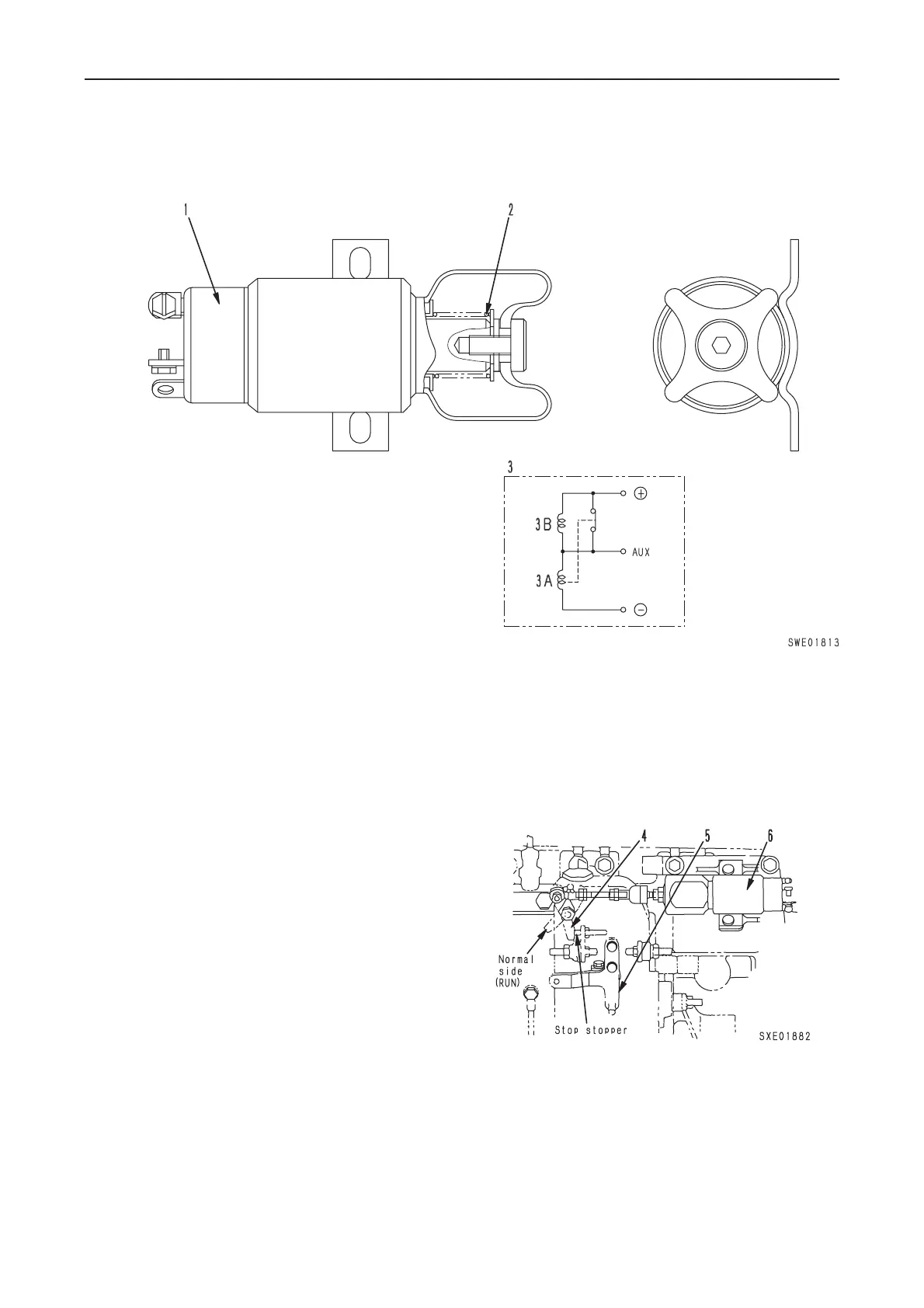
FUEL CUT SOLENOID
B CONTACT SYSTEM (CONSTANT CURRENT)
• When the engine started, electricity passes
through the solenoid and the solenoid
plunger is actuated. This extends return
spring (2) (built into the solenoid) and pulls
it to the engine run position, and holds it in
position.
• When stopping the engine, the key is turned
to the STOP position and the flow of current
through the solenoid is stopped. The mag-
netic force of the solenoid disappears, so
the force of the return spring moves the in-
jection pump stop lever to the engine STOP
position (no injection). The solenoid plunger
is also pulled back at the same time, and the
engine stops.
• The fuel injection amount is controlled by
fuel control lever (4) when the engine is run-
ning.
• Adjust length of rod when installing the fuel
solenoid valve (see TESTING AND ADJUST-
ING).
1. Case
2. Return spring
3. Internal wiring diagram
3A. C1 Attraction coil
3B. C2 Holding coil
4. Stop lever
5. Fuel control lever
6. Solenoid
Specifications
Solenoid
• Type: Synchrostart drip-proof type
• Rated voltage: DC24V
• Actuating current:
When starting to pull: Approx. 25 A
When finishing pulling: 0.5 A
• Stroke: 25.4 mm
• Weight: 1 kg
 Loading...