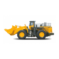
Do you have a question about the Komatsu Breathesafe WA900-3EO and is the answer not in the manual?
| Brand | Komatsu |
|---|---|
| Model | Breathesafe WA900-3EO |
| Category | Excavators |
| Language | English |
Key details about the Komatsu WA900 installation, including model, site, and system components.
Important safety precautions for operating and servicing the air conditioning system.
Details the air cleaning process, including pre-cleaning, HEPA filtration, and cabin pressurisation.
Identifies critical components of the pressuriser system and their recommended service intervals.
Describes the physical build, automatic controls, and electrical systems of the AC unit.
Provides key performance metrics, refrigerant type, and thermostat operating parameters.
Explains the core principles of heat transfer and the basic operation of an air conditioning system.
Details the air circuit, including fans and filters, and the refrigeration circuit components.
Covers evaporator, compressor, heating, and electrical circuits within the AC system.
Illustrates and describes the appearance and function of the air conditioning control panel.
Provides instructions for connecting and disconnecting the controller and outlines wiring diagrams.
Details electrical specifications, environmental operating ranges, and system protection ratings.
Guides users on adjusting air volume (fan speed) and cabin temperature settings.
Outlines procedures for starting, stopping, cooling, and defrosting the air conditioning system.
Introduces preventative maintenance and outlines daily and monthly inspection requirements for the AC system.
Lists inspection tasks required at three-monthly, annual, and 4000-hour intervals.
Outlines the maintenance schedule for the pressuriser unit, including filter and fan checks.
Provides maintenance procedures for refrigerant replenishment, coil cleaning, and fan motor checks.
Details servicing for fan blades, air filters, receiver drier, pressure switches, and thermostats.
Explains maintenance for the thermal expansion valve, compressor, and return air filter.
Summarizes technical specifications, construction details, and design methodologies used for the system.
Presents an exploded diagram and parts list for the deck-mounted condenser kit.
Displays detailed dimensional drawings and mounting information for the condenser kit.
Lists all components of the evaporator kit with their respective part numbers and quantities.
Provides an exploded view of the 24V DC TL unit, detailing individual components and hardware.
Illustrates the HEPA cabin pressuriser and its typical mounting location on the rear of the cabin.
Outlines initial commissioning steps, safety precautions, and general procedures for system setup.
Explains the process of performing a nitrogen leak test on the system following component dismantling.
Describes the necessity of a moisture-free system and the overview of the evacuation process.
Provides detailed general instructions for correctly evacuating the air conditioning system using a vacuum pump.
Details the system charging process, including ambient temperature effects and pressure guidelines.
Offers detailed general instructions for charging the AC system with refrigerant, including safety warnings.
Details the steps for powering up, checking switches, and testing cabin pressure for the pressuriser.
Introduces troubleshooting methods, compressor pressure tables, and refrigerant sight glass interpretation.
Provides a flowchart to diagnose and resolve issues when the system produces no cooling.
Offers a flowchart to diagnose and resolve problems related to the system only partially cooling.
Provides a flowchart for diagnosing and resolving issues where the system cools intermittently.
Presents a flowchart to diagnose and resolve issues causing excessive noise within the system.
Details specific fault causes and analysis notes for various system components like expansion valves and filters.
Continues fault analysis notes, covering refrigerant levels, air in system, and compressor valve issues.
Details fault finding for electronic thermostats, including wiring checks and common complaints.
Presents the system's electrical schematic diagram and a key for understanding component symbols.
Addresses pressuriser starting problems, poor performance, and causes of dust inside the cabin.
Outlines the product range warranty, including coverage periods, exclusions, and claim procedures.
Lists contact details for Breathe Safe HQ, WA branch, and the North American distributor.




 Loading...