MACHINE READY FOR ATTACHMENT ATTACHMENTS AND OPTIONS
6-12
ATTACHMENT REMOVAL AND INSTALLATION 6
Attachment Removal 6
1. Lower the attachment to the ground and stop the engine.
2. After stopping the engine, operate each control lever and attachment control pedal to the front and rear, and
left and right 2 or 3 times to the end of its stroke to release the remaining pressure inside the hydraulic circuit.
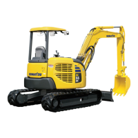
3. After checking that the oil temperature is low, rotate the
rotor of the stop valve (installed to the side face of the arm)
for the inlet and outlet port piping to the Lock position.
4. Remove the hoses on the attachment side. Install the plugs
to the two outlets.
The plugs are used to prevent the attachment from incor-
rect operation caused by mixing in of foreign matter. After
the plugs are correctly installed, store the attachment.
5. Pull out the mounting pins (2 places), remove the attach-
ment, then install the bucket.
For details of the procedure for installing the bucket, see
“BUCKET REPLACEMENT AND INVERSION (3-102)“.
6. After installing the bucket, check the oil level in the hydrau-
lic tank.
Attachment Installation 6
1. Remove the bucket.
For bucket dismounting procedure, see “BUCKET REPLACEMENT AND INVERSION (3-102)“.
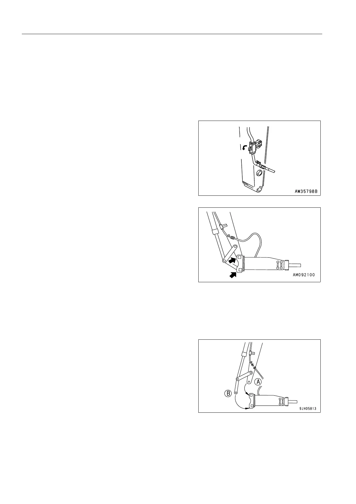
2. Place the attachment in a horizontal position, then install to
the arm with pin (A) and then pin (B).
3. After installing the attachment, stop the engine. Then oper-
ate each control lever and attachment control pedal to the
front and rear, and left and right 2 or 3 times to the end of
its stroke to release the remaining pressure inside the
hydraulic circuit.
4. After confirming low oil temperature, remove the plug from the outlet and inlet port respectively.
Take care that no dust, mud etc. adheres to the hose mouthpiece portions.
If O-ring is damaged, replace it with a new one.
Free
Lock

 Loading...