Do you have a question about the Komfovent MOU-48HFN8 and is the answer not in the manual?
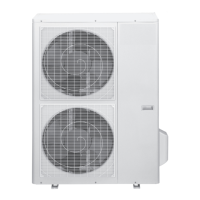
Instructions for selecting the installation location for the outdoor unit.
Requirements for refrigerant pipe length and elevation between units.
Instructions for connecting refrigerant pipes, including cutting and flaring.
Instructions for preparing and connecting cables to the outdoor unit.
Steps for evacuating the system using a vacuum pump and manifold gauge.
Guidance on refrigerant charging, including precautions and additional quantities.
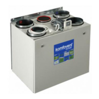
Overview of the control module and its function for AHU control.
Specifications and packing list for different AHU kit models.
Diagrams illustrating system design for AHU kits with outdoor units.
Functionality and settings for AHU kit models KA8140/KA8141.
Functionality and settings for AHU kit models KA8243/KA8245.
Settings and configuration for AHUKZ-02D controller.
Wiring diagram for connecting KA8140/KA8141 to C6 controller.
Wiring diagram for connecting KA8140/KA8141 to C6M controller.
Wiring diagram for connecting KA8140/KA8141 to C5 controller.
Wiring diagram for connecting KA8140/KA8141 to C5 zone controller.
Wiring diagram for connecting KA8243/KA8245 to C5 controller.
Wiring diagram for connecting KA8243/KA8245 to C5 zone controller.
Wiring diagram for connecting AHUKZ-02D to C5 controller.
Wiring diagram for connecting AHUKZ-02D to C5 additional zone.
Troubleshooting flowchart for E1 error (communication error).
Troubleshooting steps for E2 error (temperature sensor malfunction).
Troubleshooting steps for Ed error (outdoor unit malfunction).
Dimensional drawings for KA8140/KA8141 AHU kits.
Dimensional drawings for KA8243/KA8245 AHU kits.
Dimensional drawings for AHUKZ-02D AHU kit.
| Brand | Komfovent |
|---|---|
| Model | MOU-48HFN8 |
| Category | Air Conditioner |
| Language | English |