Do you have a question about the Kongsberg RSER200-4 and is the answer not in the manual?
Intended audience for HW engineering, hook-up and maintenance.
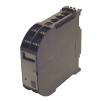
Describes the RSER200-4 module, its features, and connection types.
Details the module's power requirements and input sources.
Explains the switching principles for serial data via field channels and link channels.
Describes the function and status of the module's LEDs.
Details the USB port for test and service purposes.
Explains the watchdog timer function for software error detection.
Provides information on the module's identification label and key identifiers.
Details the RJ45 connectors for link channels, including pin allocation.
Describes the USB type B connector and its pin allocation.
Details the terminal rows for field channels, including layout and pin allocation.
Explains the RBUS connectors for power supply and their terminal allocation.
| Brand | Kongsberg |
|---|---|
| Model | RSER200-4 |
| Category | Control Unit |
| Language | English |