TECHNICAL DATA
Material
Stand tube: Steel, powder coating, black
Foot and desk Plate:
Aluminum, powder coating, black
Screws, washers: Steel, galvanized
Caps, grips, knobs: PE, PA, PUR black
Load max. 8 kg centered load
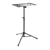
Dimensions
Base: W x D: 298 x 261mm
Desk: W x D: 304 x 265 mm
Height: 324/333 mm
Box 370 x 340 x 50 mm
Weight 1.8 kg
MAINTENANCE, CLEANING
- Care and upkeep work are always to be performed
- without the equipment on the desk watch for possible
- risks, such as pinched hands/fingers, knocking into the
- equipment, the equipment falling over.
- To care for the product, use a damp cloth and a non-
- abrasive cleaning agent.
USAGE NOTES /
FUNCTIONS
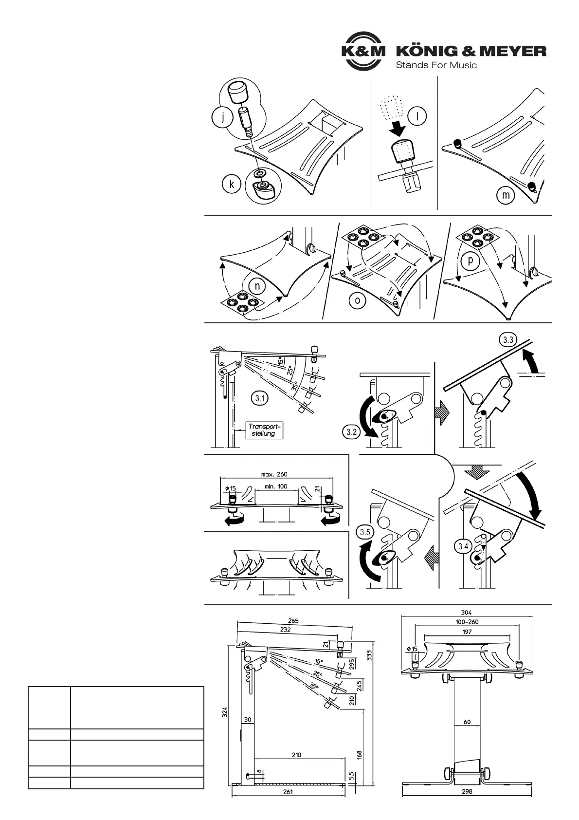
3. ADJUST THE ANGLE
3.1 Adjustable angle:
3.1 ~0° (level) - 15° - 25° - 35°
3.1 90° (collapsed = transportation position)
3.2 Loosen both wing nuts
3.3 Lift up the desk to the point that the cross bar is
3.3 located in the vertical slit
3.4 Place the cross bar in the desired slit - as far
3.4 as it will go
3.5 Re-tighten both wing nuts
4. PLACE THE EDGES
4.1 Loosen the wing nuts B.1...
4.2 …and move the bolts to the desired position
4.3 Re-tighten the wing nuts
5. VENTILATION SLITS
The four curved slits in the desk are designed to provide
improved ventilation for your equipment.
6. DIMENSIONS
FAULT-FINDING (F) and REPAIR (R)
F: Installation is not stable
F: R: Check the surface (level and weight-bearing)
F: R: Check that the equipment has been assembled
F: R: properly, is the tube secure 2.4, is the cross bar
F: R: properly in the slit 3.4.
F: R: Check and ensure that the rubber knobs C are
F: R: all there and positioned properly under the
F: R: foot plate 2.6.n
F: R: Tighten loose screw connections
F: The equipment is not secure and stable
F: R: Check the position of the bolts B, 2.5 and if
F: R: needed adjust accordingly
F: R: Check and ensure that the rubber knobs C are
F: R: all there and positioned properly on the desk 2.6.o
2.5 Take the EDGES B from the accessories bag
2.5 j Place the bolt B.3 from above through one of the
2.5 j two lower desk slits. The lateral bolt shape is
2.5 j designed to protect it from being turned and must
2.5 j disappear in the slit
2.5 k Screw the Wing nut B.1 and washer B.2 from
2.5 k below into the thread of the bolt
2.5 l Place the Rubber cap B.4 onto the bolt
2.5 m Now install the second bolt B in the other slit
2.6 Take the RUBBER KNOBS C from the
2.6 accessories bag
2.6 n Ad here 4 knobs to the corners of the underside
2.6 n of the foot plate
2.6 o The other 4 knobs are adhered to the desk, whereby
2.6 o the exact placement depends on the dimensions of
2.6 o the equipment
2.6 p In the event that an additional device is placed
2.6 p on the foot plate, 4 knobs can also be placed here
2.5 EDGES
2.6 RUBBER KNOBS
3. ADJUST THE ANGLE
4. PLACE THE EDGES
5. VENTILATION SLITS
6. DIMENSIONS
 Loading...