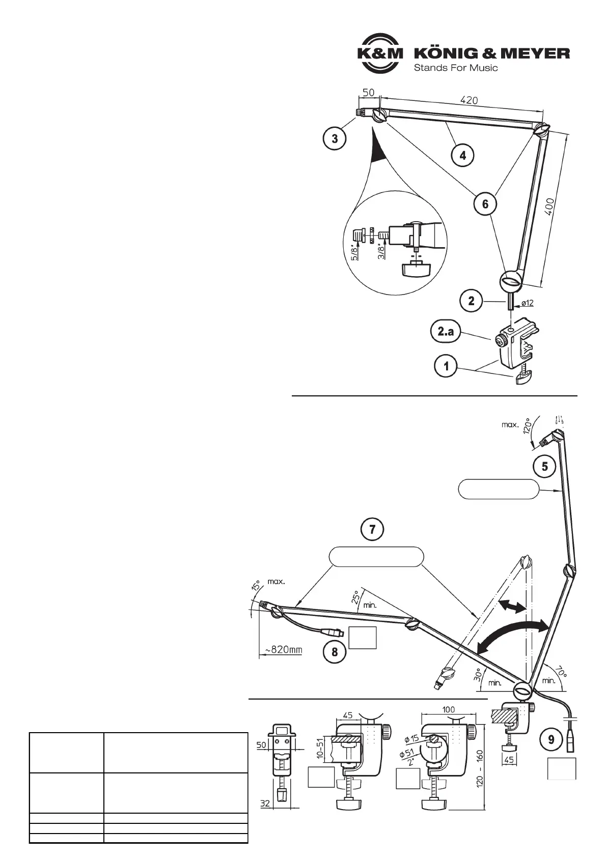
Initial position
Setting examples
Angles and dimensions
represent limit values.
MICROPHONE ARM
CLAMP
KÖNIG & MEYER GmbH & Co. KG
Kiesweg 2, 97877 Wertheim, www.k-m.de
23860-321-55 Rev.6a 03-80-419-00 3/21
INSTALLATION
OPERATING MODE
TECHNICAL DATA
1 Screw the clamp to the panel
2 Insert the rod of the microphone arm into the opening
2 of the clamp and adjust the direction of the arm
2.a Secure this position by tightening the knurled screw
3 Select threaded connection (3/8", 5/8") and attach microphone
4 Set the microphone arm as described in OPERATING MODE
The microphone arm is very adjustable. This is made possible through
the three variably adjustable joints.
Any position can be set up to the actual length of the arm.
The proper functioning of the microphone arm is based on the
interaction of three factors.
A. MICROPHONE WEIGHT
B. SPRING TENSION
C. STRENGTH OF WING NUTS 6
5 Without the microphone and when the wing nuts are not
5 tightened the arm returns to its original position through the
5 tension of the spring (vertical position).
5 The weight of the microphone acts as a counterweight to
5 the spring, such that the arm can be placed in the desired
5 position.
6 To ensure that the microphone stays in the desired position,
6 the wing nuts 6 are tightened (do not over-tighten - tighten
6 only to the point that the arm does not move by itself.
7 If the balance is correct, the microphone arm can be
7 moved inseveral desired positions - avoiding the screwing
7 and unscrewing of the wing nuts 6.
CABEL
Practical, secure and looks great:
thanks to the high quality, internal microphone cable
- the microphone arm is immediately ready for use
- Length 6 m, of that 1m in the microphone arm
8 On the microphone side: 3-pin XLR bush
9 On the mixer 3-pin XLR plug
Material
Microphone arm: Aluminum-profile, black
Springs, small parts: Steel, black
Guides, handles: Plastic, black
Clamp housing: Aluminum, PA, black
Dimensions
- max. delivery: 820 mm
- Clamp: Panels 10-51 mm,
- tubes ø 15-51 mm
- Microphone connectors: 3/8", 5/8"
Weight 1.4 kg
Box H x W x D: 535 x 150 x 80 mm
Accessories (optional) Table flange 23855
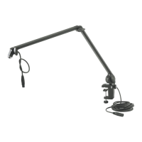
23860 Microphone desk arm
- particularly suited for broadcast studios
- for flexible positioning of studio microphones
- load-bearing capacity: up to 1.5 kg; reach: up to 0.8 m
- with internal microphone cable:
- length: 6 m, 3-pin-XLR-Connections
- with clamp (panels 10-51 mm, tubes ø 215-51 mm)
- threaded connections 3/8" and 5/8"
SAFETY INSTRUCTIONS
- Ensure a suitable support in terms of size (panels 10-51 mm,
- tube ø 15-51 mm), texture and surface.
- The table clamp 1 must be firmly fixed.
- Maximum load-bearing capacity: 1.5 kg.
BEWARE OF UNCONTROLLED MOVEMENTS
- In an unloaded condition, the springs pulls up 5 the arms of the Microphone
- holder (= starting position).
- In order to avoid this uncontrolled movement, the following measures must be
- taken before removing the microphone respectively before loosening the wing
- nuts 6 hold the microphone arm 4 with your hand or bring in initial position.
- The tightening of the three wing nuts 6 at the joints of the Microphone is NOT
- sufficient to avoid this uncontrolled movement since the spring force is too
- strong.
Thank you very much for choosing this product. Please read and follow the
instructions carefully before installing and operating this product. They inform
you about all important steps to ensure safe handling. Please keep these
instructions for future reference.
XLR
bush
Dim.
panels
Dim.
tubes
XLR
plug
 Loading...