Do you have a question about the Könner & Söhnen KS 48V-DC and is the answer not in the manual?
| DC Voltage | 48V |
|---|---|
| Output Voltage | 230V |
| Battery Capacity | 1536Wh |
| Display | LCD |
| DC Output | 1 x DC5521 (12V/10A) |
| Warranty | 2 years |
Advises users to read the full version of the manual before operating the generator.
States manufacturer reserves the right to alter specifications and that data is current at publication.
Outlines safe operating conditions, ventilation, placement, and personal protective equipment.
Warns about poisonous exhaust gases and prohibits installation in residential buildings.
Emphasizes following safety measures to avoid electric shock from generated electricity.
Warns against operating the generator when tired or under the influence of drugs or alcohol.
Specifies connection to 48-54V battery, load disconnection, unleaded gasoline use, and no refueling while running.
Warns that fuel contaminates land and groundwater and to prevent leaks.
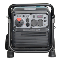
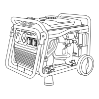
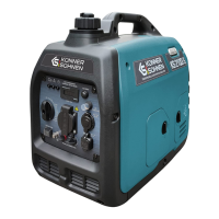
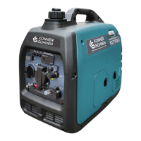
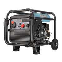
Identifies key external components of the generator.
Details the indicators, switches, and terminals on the generator's control panel.
Lists detailed technical parameters for the KS 48V-DC generator.
Describes ideal environmental conditions for maximum generator performance.
Advises ensuring the control panel and generator underside are cooled and protected from dirt/water.
Explains the function of the yellow oil level indicator and its effect on engine start.
Describes the green DC indicator light that shows when the generator is running and producing electricity.
Explains when the overload indicator lights up and the steps to take.
Notes that the overload indicator may briefly light up after start-up without being a malfunction.
Provides instructions for checking and filling the fuel tank with unleaded gasoline.
Details the procedure for checking and adding motor oil to the generator.
Warns against altering factory-set controller settings for fuel or speed governor.
Mandates connection to the network by a certified electrician according to regulations.
Lists steps for commissioning, including oil, fuel, air filter checks, and wire connections.
Advises periodic checking of terminals and forbids using cables without a fuse.
States the generator is only for battery charging and not for direct connection to consumers.
Explains how to activate and use the generator's automatic control mode.
Details the generator's start/stop triggers and reaction times in automatic mode.
Describes the error mode if the generator runs out of fuel and how to reset it.
Guides on activating manual or external control mode using a dry contact.
Outlines generator behavior (start/stop) based on dry contact status and overvoltage.
Strictly forbids connecting voltage to the control terminal wires, warning of generator failure.
Instructs to move the switch wheel to the OFF position to stop the generator in any mode.
Directs users to the website for a list of service center addresses.
Presents a table detailing maintenance tasks for motor oil, air filter, spark plug, and fuel filter.
States the manufacturer is not liable for damage due to failure to perform maintenance.
Specifies SAE 10W-30 and SAE 10W-40 oils and conditions for using other viscosities.
Provides step-by-step instructions for cleaning the air filter element.
Mentions spark plugs must be intact with correct gap and free of soot.
Details how to verify, measure, clean, and set the gap for the spark plug.
Explains how to clean the screen and flame arrester of the damper using a wire brush.
Emphasizes matching the flame arrester protrusion to the hole in the pipe damper.
Provides steps for removing, cleaning with gasoline, and replacing the fuel filter.
Warns against using gasoline while smoking or near open flames.
Details draining fuel, storage conditions (dry, dust-free, temperature), and avoiding direct sunlight.
Advises recycling the generator properly to prevent environmental damage.
Lists common reasons and solutions for the engine not starting.
Provides possible causes and solutions for low engine power, heavy starting, and overheating.
Offers solutions for no voltage output and connected devices not working.
Explains the 1-year international warranty, local dealer responsibility, and repair/exchange policy.
Lists necessary documentation and conditions for warranty repair, including a valid warranty card.
Provides contact details for DIMAX International GmbH in Germany.
Provides contact details for DIMAX International Poland Sp.z o.o.
Provides contact details for TOV «Techno Trade KS» in Ukraine.