The INVEOR P Drive Controller, manufactured by KOSTAL Industrie Elektrik GmbH, is a versatile device designed for speed control in three-phase AC motors. This operating manual, document number DOC01695343-0001, dated March 2016 (V2.00 EN), provides comprehensive information for its installation, commissioning, operation, and maintenance.
Function Description:
The INVEOR P Drive Controller serves as a speed control unit for three-phase AC motors. It is designed to be universally compatible with all common motor types. The device is offered in various sizes (Alpha, A, B, C, D) and configurations, including different grid voltages (230 V and 400 V), recommended motor ratings (from 0.75 kW to 22.00 kW), and options for power-conducting plates (with or without brake chopper) and application PCBs (Standard, Basic, CANopen, EtherCAT, PROFINET, Sercos III, PROFIBUS COMX). The controller's output stage is enabled either by activating a 230 V AC or 325 V DC mains supply (for Alpha size), or a 400 V AC or 565 V DC mains supply (for A-D sizes), or by connecting an external 24 V voltage.
Important Technical Specifications:
The INVEOR P series offers a range of models with varying power outputs and cooling requirements.
- Sizes and Motor Ratings:
- Alpha, 1 x 230 VAC: up to 0.75 kW
- A, 1 x 230 VAC: up to 1.5 kW
- A, 3 x 400 VAC: up to 1.5 kW
- B, 3 x 400 VAC: up to 4.0 kW
- C, 3 x 400 VAC: up to 7.5 kW
- D, 3 x 400 VAC: up to 15 kW and up to 22 kW
- Mains Voltage: 1 x 100 VAC – 15% to 230 VAC + 10% for 230 V devices; 3 x 200 VAC – 10% to 480 VAC + 10% for 400 V devices.
- Mains Frequency: 50 Hz / 60 Hz ± 6%.
- Maximum Overload: 150% of nominal current for 60 seconds (for Alpha, A, B, C) and 130% of nominal current for 60 seconds (for D).
- Switching Frequency: 4 kHz, 8 kHz, 16 kHz (factory setting 8 kHz).
- Protection Type: IP 00 (the final application determines the actual protection type).
- EMC: Prepared for satisfying DIN EN 61800-3, class C1 or C2, depending on the model.
- Dimensions (L x W x H): Ranging from 210x120x71 mm (Alpha) to 343x270x113 mm (D).
- Weight (including cooling plate): From 1.6 kg (Alpha) to 6.5 kg (D).
- Digital Inputs (1-4): Switching level low < 5 V / high > 15 V, Imax (at 24 V) = 3 mA, Rin = 8.6 kOhm.
- Analogue Inputs (1, 2): In +/- 10 V or 0 – 20 mA, 10-bit resolution, tolerance +/- 2%.
- Digital Outputs (1, 2): Short-circuit proof, Imax = 20 mA.
- Relays (1, 2): 1 changeover contact (NO/NC), maximum switching power at ohmic load (cos ϕ = 1): 5 A at 1 AC 230 V or = 30 V; at inductive load (cos ϕ = 0.4 and L/R = 7 ms): 2 A at 1 AC 230 V or = 30 V. Maximum reaction time: 7 ms ± 0.5 ms. Electric life: 100,000 switching cycles.
- Power Supply (24 V): Auxiliary voltage U = 24 V DC, short-circuit proof, Imax = 100 mA. External feeding of 24 V possible.
- Power Supply (10 V): Auxiliary voltage U = 10 V DC, short-circuit proof, Imax = 30 mA.
Usage Features:
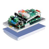
- Installation: The drive controller is designed for installation in housings that comply with at least degree of contamination 2. For optimal heat transfer, the surfaces between the installation plate (Cold Plate) and the customer-provided cooler must be coated with thermal conductivity paste (layer thickness 30 – 70 µ). The manual specifies the evenness (0.05 mm) and maximum roughness (RZ 6) required for the contact surface.
- Cooling: The INVEOR P can be cooled by a sufficiently large installation plate or an additional cooler. Active cooling is recommended for size D to reduce the size of the cooling element. The device includes "IGBT temperature" and "Interior temperature" shutdown thresholds (95 °C and 85 °C respectively) to prevent damage from inadequate cooling.
- Safety: The device must be de-energized and secured against restarting before any work. A two-minute discharge time for capacitors is required after shutdown. Proper grounding according to DIN EN 61140 and VDE 0140 is mandatory. The INVEOR P may have touch currents > 3.5 mA, necessitating an extra protective grounding conductor. Universal current sensitive RCDs (type B) are required for three-phase frequency inverters.
- Wiring: Shielded lines are recommended for control circuits, routed away from power lines. EMC cable screw connections are advised for power connections between the drive controller and motor, with shielding grounded at both ends.
- Brake Resistors: For safe operation of the "brake chopper" option, inherently safe, wire-based brake resistors must be used to prevent short circuits, earth faults, fire, explosion, or melting of the resistor housing during long-lasting overloads.
- Motor Protection: The drive controller has internal motor overload protection (I²T settings, parameters 33.010 and 33.011, ON by default) and can also be protected via an external PTC. Only motor PTCs corresponding to DIN 44081/44082 may be connected.
- Commissioning: Detailed commissioning instructions are available in separate operating manuals for INVEOR Alpha and INVEOR A-D, downloadable from the KOSTAL website.
- Parameterization: Parameters for the INVEOR P (Alpha and A-D sizes) are described in separate, detailed operating manuals available for download.
- Troubleshooting: Error detection and troubleshooting information is provided in dedicated chapters within the detailed operating manuals for INVEOR Alpha and INVEOR A-D.
- Optional Accessories: The device supports various optional accessories, including an MMI handheld controller for parameterization, PC communication cables (USB on M12/RS485 plug), adapter cables, internal potentiometers, and CANopen, PROFIBUS, EtherCAT/PROFINET/Sercos III connection cables. Thermal conductivity paste (art. no. 10139778) is also available to improve heat transfer.
Maintenance Features:
- Qualified Staff: Maintenance and inspection must only be performed by electricians with recognized training.
- Repairs: Repairs to the drive controller are exclusively to be performed by the KOSTAL Service department. Independent and unauthorized interventions void the warranty and can lead to serious hazards.
- Insulation Resistance: An insulation test on the control card's input terminals is not permitted.
- Cooling Element: Ensure the drive controller's cooling elements and neighboring parts are allowed to cool sufficiently before handling to prevent burns. Protection against accidental contact may be necessary.
- Documentation: The operating manual must be kept close to the drive controller for easy access by all users. All warning signs on the device must be legible and replaced if missing or damaged.