Do you have a question about the KPS KPS-MT30 and is the answer not in the manual?
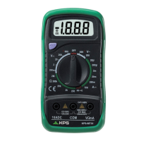
Features a 3 1/2 digit, 7 segment, 15mm high LCD.
Selects functions, ranges, and powers the meter on/off.
Input for red test lead for voltage, resistance, and current measurements.
Input for black (negative) test lead.
Input for red test lead for 10A current measurements.
Freezes the displayed reading on the LCD.
Meter designed per IEC 61010, CAT.III 600V, pollution grade 2. Follow instructions for safe operation.
Indicates critical safety information requiring manual reference.
Warns of the presence of hazardous voltages.
Denotes protection class II equipment.
Indicates a connection to earth ground.
Disconnect leads from circuits before opening the case.
Specifies fuse types and ratings for replacement.
Ensure the back cover is fastened before operation.
Use a damp cloth and mild detergent; avoid abrasives.
Specifications for internal fuses: F1 (250mA) and F2 (10A).
Operates on a 9V battery (NEDA 1604 or 6F22).
LCD with 1999 counts, updates 2-3/sec.
Utilizes dual-slope integration A/D converter.
Overrange shown as '1', negative polarity as '-'.
Operates 0-40°C, stores -10-50°C.
Low battery indicator, dimensions, and weight.
Step-by-step guide for measuring DC voltage.
Step-by-step guide for measuring DC current.
Step-by-step guide for measuring AC voltage.
Step-by-step guide for measuring resistance.
Step-by-step guide for testing diodes.
Step-by-step guide for testing continuity with audible feedback.
Symbol indicating that the battery should be replaced.
Fuses rarely need replacement; blows usually due to operator error.
Details specific fuse types and ratings for replacement.
Instructions for removing screws and replacing components.
Important note to observe correct battery installation polarity.
Operator's instruction manual.
Set of test leads included with the multimeter.
Protective holster for the multimeter.
The manufacturer guarantees the device for 2 years against manufacturing defects.
| Brand | KPS |
|---|---|
| Model | KPS-MT30 |
| Category | Multimeter |
| Language | English |