Do you have a question about the Kracht KFF 2.5-630 and is the answer not in the manual?
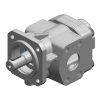
The KRACHT KFF 2.5-630 gear pump is an external gear pump designed for the displacement principle, primarily for operation with fluids. Dry operation is not permitted, and the pump must always be completely filled during use. It is specifically developed for fuels, particularly marine fuels like diesel (MGO/DMA), which often exhibit low lubricity. The pump's performance with such fuels is assessed using the Wear Scar Diameter (WSD) determined by the HFRR test (ISO 12156).
The pump operates with two interlocking gears. During rotation, the tooth spaces on the suction side (S) open, increasing volume and allowing the medium to flow in. Simultaneously, on the discharge side (P), a corresponding volume is displaced by the meshing teeth in the filled tooth gaps. Fluid transport occurs through entrainment in the tooth spaces along the wall of the wheel chamber. Each gear rotation displaces a geometric volume (Vgn), which is the rated volume used to specify the pump size. Pressure build-up occurs only when external loads, such as head, flow resistances, or pipe elements, are applied. The pressure at the shaft seal is equal to the pressure at the suction connection, and the permissible pressure is determined by the seal type.
The KFF 2.5-630 series offers a wide range of nominal sizes, from 2.5 to 630 cm³/U (geometric displacement volume). Housing connections vary by nominal size:
Mounting positions include "Any" for pumps without a fluid buffer and "Shaft end horizontal, fluid buffer connection top" for pumps with a fluid buffer. Axial forces are not permissible on the shaft end, and radial forces are only permissible in combination with roller bearings.
The permissible operating pressure (Pe) and pressure peaks (Pb) vary depending on the seal type and nominal size. For seal types 2, 5, and 7, the maximum relative suction pressure (Pe max) is 10 bar, with an absolute minimum (Pe min) of 0.6 bar (0.4 bar absolute for max. 30 minutes during start-up). For seal type 74, Pe min is 0.1 bar absolute, and Pe max is 0.2 bar relative. The permissible continuous pressure (Pb) is 25 bar, with pressure peaks up to 40 bar.
The pump supports a wide range of kinematic viscosities, from 100 mm²/s at 3600 rpm to 20000 mm²/s at 200 rpm. The maximum permissible viscosity (Vmax) is 20000 mm²/s. Differential pressure to viscosity assignments for plain bearings vary: for v=1.4 mm²/s, Δpmax is 3 bar; for v=6 mm²/s, Δpmax is 12 bar; and for v=12 mm²/s, Δpmax is 25 bar. For fuels (WSD ≤ 520 µm) with plain bearings, Δpmax is 12 bar at v=1.2 mm²/s.
The permissible fluid temperature (θm) ranges from -20 °C to 150 °C. The permissible ambient temperature (θu) ranges from -20 °C to 60 °C.
Common materials include FKM for shaft seals and O-rings. Housing, end cover, and valve housing are typically EN-GJS-400-15. Gears are made of case-hardened steel (16MnCrS5 / 1.7139). Plain bearings are multi-layer friction bearings containing lead (Steel (St), CuSn, PTFE, Pb).
The pump is designed for lubricating fluids without abrasive components. Petrols, solvents, and similar substances are not permissible. It can handle fuels with a WSD ≤ 520 µm, compliant with ISO 8217 for marine fuels.
The pump can be configured with various seal types, including rotary shaft seals (FKM BABSL, double FKM BABSL) and mechanical seals (FKM secondary seals AX30, L4, AQ2VFF). Fluid seals are used when absolute leak tightness is required, such as when pumping media that harden or crystallize on contact with air, or when under vacuum. The fluid seal connection should be installed at the top. The direction of rotation is indicated by a curved arrow when looking at the drive shaft end, with pump connections below the drive shaft. The flow direction is indicated by a straight arrow. Pressure relief valves can be integrated, with setting ranges from 0-15 bar (D15, T15) to 15-30 bar (D30) or 15-25 bar (D25, T25). Viscosity ranges for pressure relief valves with tank connection are 12-300, 300-1000, and 1000-5000.
Installation requires careful attention to cleanliness, proper alignment of coupling parts, and secure fastening. Suction lines should be as short and straight as possible, with adequate nominal size to prevent cavitation. For vacuum operation, the pump should be positioned approximately 1 meter below the tank, and the suction line should be straight and free of resistances. If the suction line can run dry, a U-trap or foot/non-return valve is recommended to keep the pump filled. Commissioning involves ensuring sufficient service fluid, checking fastening screws, filling the pump and suction line, and filling the quench chamber for fluid seal versions. Pressure relief valves are factory-set but can be adjusted. Directly attached series D pressure relief valves are for pump protection and short-term operation only, while series T valves can control system pressure. Initial start-up should be without pressure load or at low pressure, gradually increasing to the required operating pressure.
Regular maintenance is crucial for the pump's longevity. A maintenance table outlines checks at various intervals:
Maintenance work includes replacing defective or worn components, documenting operating data, and comparing it with initial commissioning values. In case of significant deviations, the cause must be determined. Wearing parts should be replaced before reaching their wear limit. Plain bearings are replaced only by the manufacturer. The outboard bearing should be checked for damage after 4000 hours.
The manual provides a comprehensive fault table to address common issues like increased noise, pump cavitation, foaming or air in media, mechanical vibrations, pump not sucking, insufficient pressure, and excessive operating temperature. Solutions range from checking line design and fluid levels to replacing seals and adjusting operating parameters. For unidentifiable faults, consulting the manufacturer is recommended.
The pump is factory-tested with mineral hydraulic oil, and connections are closed. Residual oil preserves internal parts for up to 6 months. External metallic parts are protected against corrosion. Storage should be in a dry, dust-free, low-vibration environment, protected from weather, moisture, and large temperature fluctuations. Elastomer seals have specific maximum storage periods (e.g., 5 years for AU, 7 years for NBR/HNBR/CR, 10 years for EPM/EPDM/FEP/PFTE/FEPM/FKM/FFKM/VMQ/FVMQ). Products with EPDM seals require special preservation if not immediately put into operation, as they are not mineral oil resistant. Storage in corrosion protection bags (VCI) is recommended for a maximum of 6 months.
| Brand | Kracht |
|---|---|
| Model | KFF 2.5-630 |
| Category | Water Pump |
| Language | English |