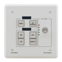
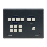
Display the name of each button group; programmed via the K-Config configuration software
Programmed for distinct functions via the K-Config configuration software
Lights red to indicate maximum volume
Light according to the volume level
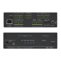
Connects to the Ground, RS-485 communication, and power supply
Note: The Ground is sometimes connected to the shield of the RS-485 cable.
RS-232 Port (GND, Rx,
Tx)
Connects to A/V equipment, PC or serial controller
Controls a device via an IR Emitter
Connect to room items such as lighting and screen settings
Connects to grounding wire (optional)
Connects to a computer for system configuration, firmware upgrade, or setting the K-NET ID no.
IR IN built-in IR
Receiver
Used to learn the IR commands from a machine’s remote control transmitter.
For technical support use only.
Note: Should be set in the direction of the arrow for normal operation.
Controls K-NET bus termination:
• Push the switch in the direction of the arrow to terminate.
• Push the switch away from the direction of the arrow to leave unterminated.
Note: The last physical device on a K-NET bus must be terminated.
To access the K-NET termination switch, insert a small screwdriver into the gap between the rear panel PCB and
the metal rear panel cover.
To reset memory to the factory default K-NET ID auxiliary setting (ID=2), disconnect the power and then reconnect it
while using a small screwdriver to press the RESET TO DEFAULT button.
Note: This operation should be carried out by authorized Kramer technical personnel or by a qualified system
integrator.
To access the RESET TO DEFAULT button, insert a small screwdriver into the gap between the rear panel PCB
and the metal rear panel cover.
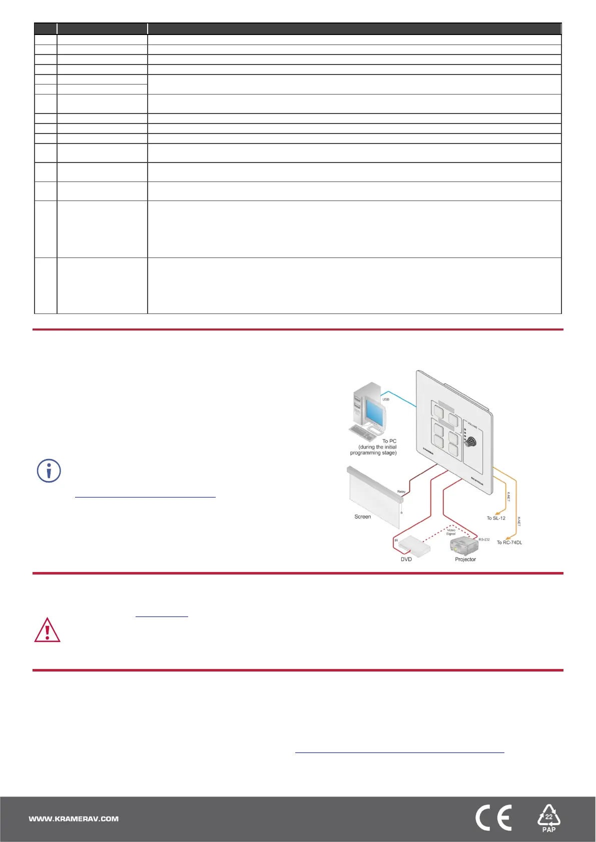
Step 3: Connect inputs and outputs
Always switch OFF the power on each device before connecting it to your RC-63DLN.
1. Connect the inputs and outputs to their appropriate devices
using terminal block connectors (see example on the right):
▪ I/O ports: 1 RS-232, 2 K-NET
▪ Outputs: 1 infrared, 2 relays
2. Connect 12V DC power to the unit if power is not available
over the K-NET.
3. Mount the unit in a wall.
To achieve specified extension distances, use the recommended Kramer
cables available at
www.kramerav.com/product/RC-63DLN.
Using third-party cables may cause damage!
Step 4: Connect power
Connect the power cord to RC-63DLN and plug it into the mains electricity.
Safety Instructions (See www.kramerav.com for updated safety information)
Caution:
• For products with relay terminals and GPI\O ports, please refer to the permitted rating for an external connection, located next to the terminal or in the User Manual.
• There are no operator serviceable parts inside the unit.
Warning:
• Use only the power cord that is supplied with the unit.
• Disconnect the power and unplug the unit from the wall before installing.
Step 5: Operate RC-63DLN
Operate the unit via the front panel buttons or remotely by AUX. keypad over K-NET.
Note: By default, the RC-63DLN is set up as an auxiliary device.
Configure and customize the RC-63DLN
• Configure the unit using K-Config software, available at www.kramerav.com/support/product_downloads.asp.
• Customize the buttons by inserting the appropriate labels under the button caps.
 Loading...