Install TP-580CT using one of the following methods:
• Attach the rubber feet and place the unit on a flat surface.
• Fasten a bracket (included) on each side of the unit and attach it to a flat surface
(see www.kramerav.com/downloads/TP-580CT).
• Mount the unit in a rack using the recommended rack adapter
(see www.kramerav.com/product/TP-580CT).
• Ensure that the environment (e.g., maximum ambient temperature &
air flow) is compatible for the device.
• Avoid uneven mechanical loading.
• Appropriate consideration of equipment nameplate ratings should be
used for avoiding overloading of the circuits.
• Reliable earthing of rack-mounted equipment should be maintained.
• Maximum mounting height for the device is 2 meters.
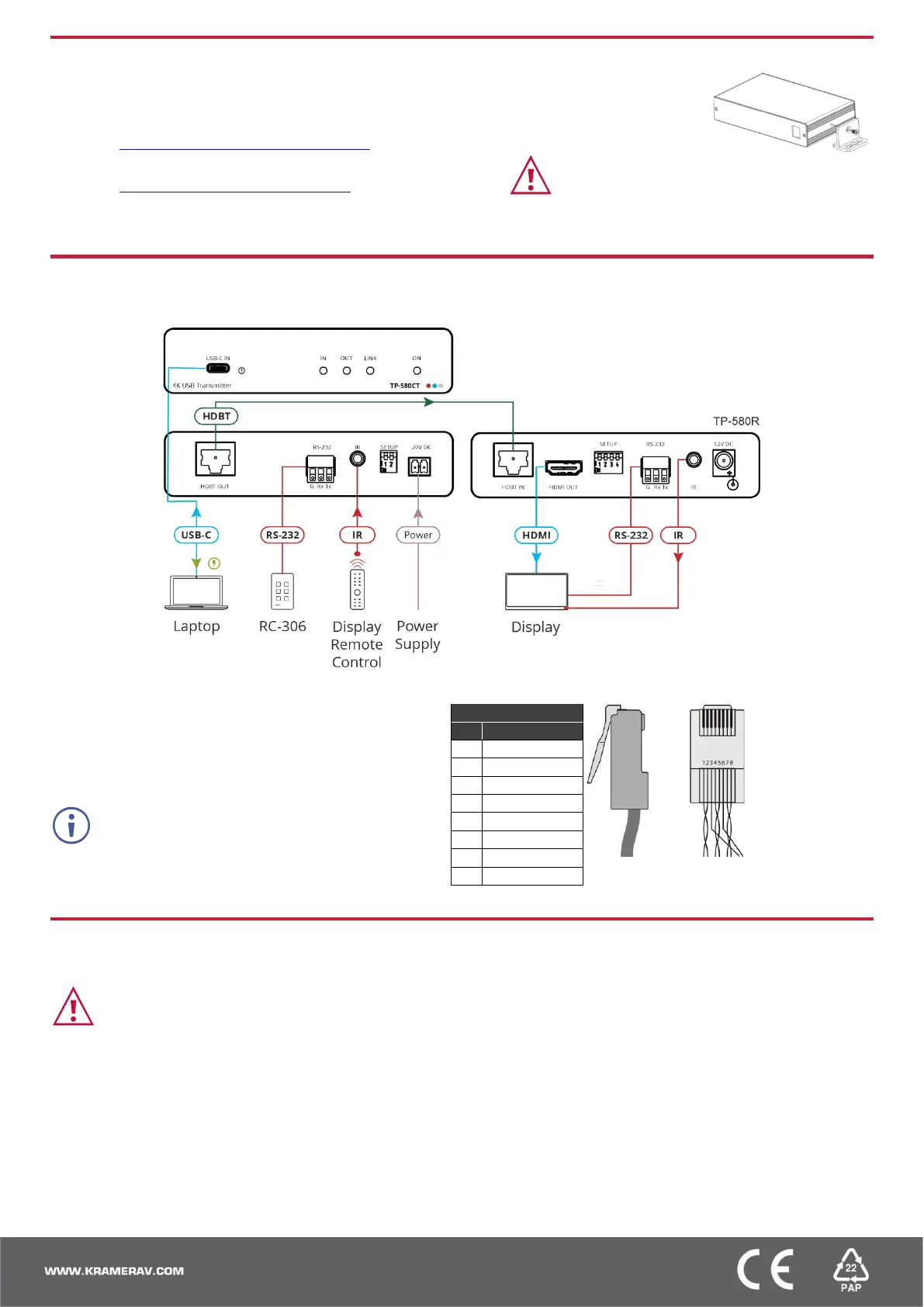
Step 4: Connect inputs and outputs
Always switch OFF the power on each device before connecting it to your TP-580CT.
Wiring the RJ-45 Connectors
This section defines the TP pinout, using a straight pin-to-pin
cable with RJ-45 connectors.
For HDBT cables, it is recommended that the cable ground
shielding be connected/soldered to the connector shield.
Step 5: Connect power
Connect the adapter to TP-580CT and plug it into the mains electricity.
Safety Instructions (See www.kramerav.com for updated safety information)
Caution:
• For products with relay terminals and GPI\O ports, please refer to the permitted rating for an external connection, located next to the terminal or in the User Manual.
• There are no operator serviceable parts inside the unit.
Warning:
• Use only the power cord that is supplied with the unit.
• Disconnect the power and unplug the unit from the wall before installing.
 Loading...