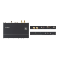
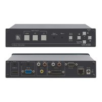
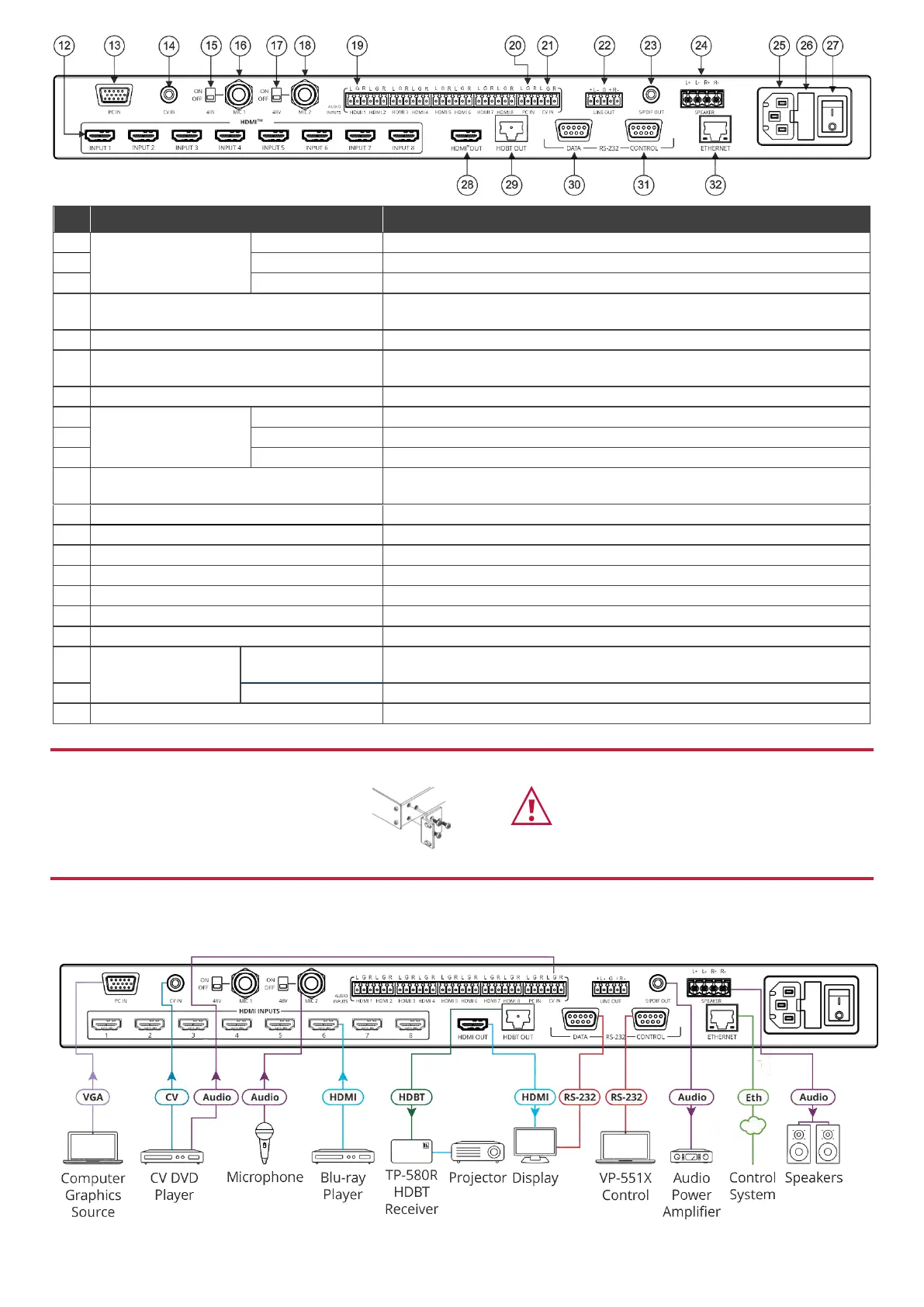
Connect to an HDMI source (from INPUT 1 to INPUT 8).
Connect to a computer graphics source.
Connect to a composite video source.
Move up (ON) to select a condenser type microphone; down (OFF) to select
a dynamic type microphone.
Connect to the microphone source 1.
Move up (ON) to select a condenser type microphone; down (OFF) to select
a dynamic type microphone.
Connect to the microphone source 2.
AUDIO INPUT
Unbalanced Stereo
Terminal Blocks
Connect to an analog audio HDMI source (from 1 to 8).
Connect to an analog audio computer graphics source.
Connect to an analog audio composite video source.
LINE OUT Balanced Stereo 5-pin Terminal
Block Connector
Connect to a balanced stereo analog audio acceptor.
S/PDIF OUT 3.5 Mini Jack Connector
Connect to a digital audio acceptor.
Speaker Terminal Block Connector
Connect to a pair of loudspeakers.
Connect the mains power cord.
Fuse for protecting the device.
Switch for turning the unit ON or OFF.
Connect to the HDMI acceptor.
Connect to an HDBaseT receiver.
RS-232 9-pin D-sub
Connector
Connect to a PC or controller to tunnel RS-232 via HDBT OUT or connect to
the output display to control it.
Connect to a PC or remote controller to control VP-551X.
Connects to the PC or other Serial Controller through computer networking.
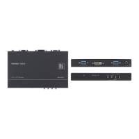
Step 3: Install the VP-551X
To rack mount the machine, attach both rack ears
(by removing the screws from each side of the
machine and replacing those screws through the
rack ears) or place the machine on a table.
• Ensure that the environment (e.g., maximum ambient temperature &
air flow) is compatible for the device.
• Avoid uneven mechanical loading.
• Appropriate consideration of equipment nameplate ratings should be
used for avoiding overloading of the circuits.
• Reliable earthing of rack-mounted equipment should be maintained.
Step 4: Connect the inputs and outputs
Always switch OFF the power on each device before connecting it to your VP-551X. For best results, we recommend that you
always use Kramer high-performance cables to connect AV equipment to the VP-551X.
Condenser Microphone Pinout
Dynamic Microphone Pinout
 Loading...