EasyManua.ls Logo

KRILL AIRCRAFT LASER Z2300 Mk2 - User Manual

KRILL AIRCRAFT LASER Z2300 Mk2
14 pages
Print Icon
To Next Page IconTo Next Page
Loading...
1
LASER Z2300 Mk2 39%
Assembly Guide
Dear customer,
thank you for choosing LASER Z2300 Mk2 39% model airplane.
Original kit Laser Z2300 was developed by our team for Freestyle flight. Kit has had great flying
characteristics, but not sufficient for top competitive flying. We decided to improve it‘s flying
characteristic and thats why we created new version Mk2 built on strong base of current kit and test
it with our pilot Marek Plichta.
And what are the differencies?
At first, we made new bigger wings. Kit gets incredible flying agility also during harier manuvers..
Interier of the fuselage is also improved, holder of tanks which you can buy it with the plane and
already instaled rudder servo tray which you can extend with bearing arm. Holder of main landing
gear is also redesigned and for all control surfaces we used Gabriel horns.
The LASER Z2300 Mk2 kit is a full composite kit. Both wings and elevator should be easily
removed for transporting.
Content page
1. Technical data ............................................................................................................................ 2
2. General informations................................................................................................................. 2
3. Setting and setup ..................................................................................................................... ..3
4. Recommended servos ............................................................................................................. ..4
5. Assembly ................................................................................................................................... 4
5.1 Empenage .................................................................................................................... 4
5.1.1 Rudder .......................................................................................................... 4
5.1.2 Horizontal stabilizator .................................................................................. 5
5.1.3 Elevator ........................................................................................................ 6
5.2 Wing assembly ............................................................................................................ 7
5.2.1 Servo install .................................................................................................. 7
5.2.2 Linkage ......................................................................................................... 8
5.3 Fuselage ..................................................................................................................... . 9
5.3.1 Rudder drive linkage .................................................................................. 9
5.3.2 Engine installation ..................................................................................... 10
5.3.3 Fuel & Smoke Tank installation ................................................................ 11
5.3.4 Equipment installation ................................................................................ 12
5.4 Landing gear .............................................................................................................. 12
5.4.1 Main landing gear ....................................................................................... 12
5.4.2 Tail wheel ................................................................................................... 14
5.5 Cowling and Cooling ............................................................................................... 15
Question and Answer IconNeed help?

Do you have a question about the KRILL AIRCRAFT LASER Z2300 Mk2 and is the answer not in the manual?

Overview

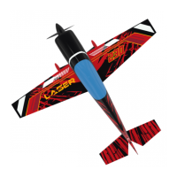
The KRILL AIRCRAFT LASER Z2300 Mk2 39% is a full composite model airplane kit designed for freestyle flight, an improved version of the original Laser Z2300. This Mk2 version features larger wings for enhanced agility, especially during "harier maneuvers," and an improved fuselage interior. The kit is designed for easy transport, with both wings and the elevator being easily removable.

Function Description

The LASER Z2300 Mk2 is a high-performance model airplane intended for experienced pilots. Its primary function is to provide a robust and agile platform for freestyle and competitive flying. The design emphasizes flight characteristics, control precision, and ease of assembly. The kit includes pre-drilled holes and prepared locations for components, simplifying the build process.

Important Technical Specifications

  • Wingspan: 2800 mm
  • Length: 2662 mm
  • Weight (RTF): 17 - 18 kg
  • Wing area: 132.5 dm2
  • Engine (Gas): 150-180ccm (2-cylinder boxer type recommended, e.g., MVVS 175NP)
  • Minimum RC channels: 6
  • Number of servos: 9 - 11

Recommended Servos:

  • Any strong and fast servos in standard size.
  • Recommended torque: min 35 kg/cm
  • Recommended speed: 0.08 – 0.11 s5.

Recommended Secraft Parts (Order Numbers):

  • 2051000-50 for Hitec servos
  • 2051000-51 for Futaba servos
  • 2051000-52 for JR servos
  • Servo arm D45 mm (for elevator): 2 units
  • Double servo arm Offset D90mm (for rudder): 1 unit
  • Double servo arm D64mm (for rudder): 1 unit
  • SEC Ball link M3 (10): 8 units
  • SEC M3 Push rod of ALU 60 mm: 8 units
  • Servo arm D40 mm (for ailerons): 4 units
  • Rudder pull-pull set BASE No.: 2050130-01 or SPORT Set No.: 2010130-02
  • Servo holder S: 2050020 for throttle servo
  • Secraft turnbuckle ALU pushrod 60 mm (for elevator linkage)
  • Secraft V2 servo arms (45 mm for elevator linkage)
  • Secraft square tanks - SE Fuel tank 1000 ml (for fuel and smoke tanks)
  • Tail wheel 2010300-81 Tail wheel 35% with leg of C / F V2

Control Surface Deflections (Basic Setup):

  • Ailerons: 20 degrees, expo 50 – 60%
  • Elevator: 30 degrees, expo 50 – 60%
  • Rudder: 30 degrees, expo 50 – 60%

Control Surface Deflections (Idle 1 for 3D):

  • Ailerons: 35 degrees, expo 60 – 70%
  • Elevator: 40 degrees, expo 60 – 70%
  • Rudder: 40 degrees, expo 60 – 70%

Control Surface Deflections (Idle 2 for 3D):

  • Ailerons: 42 – 45 degrees, expo 70 – 80%
  • Elevator: 60 degrees – full, expo 70 – 80%
  • Rudder: 50 degrees – full, expo 70 – 80%

Usage Features

Assembly: The assembly process involves several key steps:

  1. Empennage:

    • Rudder: Gabriel horns (6/20 size) are glued into prepared holes using epoxy resin.
    • Horizontal Stabilizer: Servos are placed, and holes for servo levers are drilled, ensuring sufficient space for full movement. The horizontal stabilizer is secured against motion by drilling a hole through its surface and carbon fiber tube (stabilizer spar) and inserting a pin or screw. This must be done on both halves.
    • Elevator: Gabriel horns (6/27 size) are glued into pre-drilled holes on both elevators. Linkage uses a Secraft turnbuckle ALU pushrod 60 mm long, with a Secraft ball link M3 on one side and an original Gabriel ball link on the other. The overall length of the link is 80 mm, and 45 mm ALU Secraft V2 servo arms are used.
  2. Wing Assembly:

    • Servo Installation: Servos are placed and fixed with screws into prepared holes. The cable (ONE4TWO) is stretched through prepared holes in the wing and connected to the servos. The MPX connector is fixed to a 3D printed holder, which is then fixed into its prepared hole.
    • Servo Arms: Holes for servo arms are drilled, enlarging the small pre-existing holes to fit the arm.
    • Horns: Gabriel horns are glued into the prepared holes in the ailerons.
    • Linkage: Gabriel horns (6/27 size) are glued into prepared holes with epoxy resin. Servo arms are connected to the Gabriel horns using a 60 mm pushrod, terminated with an original ball link from the Gabriel horn on one side and a Secraft ball link on the other.
  3. Fuselage:

    • Rudder Drive Linkage: Two standard servos are mounted on the already glued deck to drive the rudder. The rear servo is equipped with a Secraft double-sided offset arm 90 mm. The front servo is equipped with a Secraft double-sided straight arm 64 mm. The arms are interconnected by linkages formed by ball links, Secraft, and pushrods 70 mm. The drive itself is solved by a pull-pull drive using a Secraft Rudder pull-pull set BASE or SPORT.
    • Engine Installation: The kit accommodates 2-cylinder boxer engines (150-180 ccm). The engine is mounted offset to the right by 2.5 degrees, horizontally at zero. Spacers of suitable length are used to ensure the prop hub plane is 2-3 mm in front of the engine cover plane, respecting engine misalignment. The engine axis at the prop hub level should intersect the vertical axis of the model fuselage. Silencers, including cup-type or those with headers, can be used. A supplied 70 mm diameter muffler exhaust holder is provided. The carburetor servo is placed under the engine using a Secraft side servo mount. The engine ignition is placed on the side sloping wall of the firewall.
    • Fuel & Smoke Tank Installation: A standard delivered holder designed for Secraft square tanks (SE Fuel tank 1000 ml) is used. Tanks are attached to the holder with Velcro.
    • Equipment Installation: The fuselage is prepared for mounting electronic components. Battery holders (for 2x RX batteries and 1x ignition battery) are standardly delivered. The manual shows examples of equipment installation with JETI models electronics.
  4. Landing Gear:

    • Main Landing Gear: The chassis leg and wheel cover fit precisely. Holes for axles are drilled in both undercarriage legs. A notch is made in the wheel cover to slide it onto the axle. Wheels are installed with the axle on the chassis leg, then the wheel cover is slid on before final tightening. The landing gear leg cover is fixed to the fuselage with transparent adhesive tape. SLH Wheels 100mm on ALU disc with ball bearings are recommended.
    • Tail Wheel Assembly: The recommended tail wheel is the 2010300-81 Tail wheel 35% with leg of C / F V2. It is attached to the reinforced tail of the fuselage using 2 M4x20 screws into fixed M4 nuts in the plywood. 4 mm diameter holes are drilled into the CF leg of the tail wheel. The tail wheel does not necessarily need to be controlled by the rudder linkage; it can be left free.
  5. Cowling and Cooling:

    • The engine cover (cowling) is delivered as removed from the mold. It is folded with the fuselage, and holes for connecting screws are pre-made. Additional holes for engine cooling and carburetor air access should be made in the bottom of the engine cover, as shown in the manual (modification for MVVS175NP engine).

Setting and Setup:

  • CG (Center of Gravity): The CG should be in the center of the tube.
  • Control Surface Deflections: Specific deflection angles and expo settings are provided for basic setup, as well as two different 3D flight modes (Idle 1 and Idle 2).

Maintenance Features

  • General Information:

    • All nuts should be secured against loosening using Loctite 243.
    • Ensure all control surfaces can move freely.
    • All holes drilled in airplane surfaces must be reinforced (with rowing, plywood, etc.) as they are not factory-made.
    • Protect the airplane against heat (it can cause material degradation). Do not leave the dark surface under direct sunlight above 90°C/194°F in sunny summer days. Use protective coats (available from the kit or separately via sales@krill-model.com).
    • Place the receiver far enough from other carbon fiber in your model to ensure a full signal.
  • Cleaning: Regular cleaning of the model is recommended to remove dirt and debris, especially from control surfaces and linkages, to ensure smooth operation.

  • Inspection: Before each flight, inspect all connections, linkages, and structural components for any signs of wear, damage, or looseness. Pay close attention to servo mounts, horn attachments, and engine mounting.

  • Battery Management: Ensure proper charging and maintenance of all batteries (RX and ignition) according to manufacturer guidelines.

  • Engine Maintenance: Follow the engine manufacturer's recommendations for maintenance, including fuel mixture, spark plug checks, and general engine care.

  • Storage: Store the model in a cool, dry place, away from direct sunlight and extreme temperatures, to prevent material degradation. The removable wings and elevator facilitate compact storage and transport.

KRILL AIRCRAFT LASER Z2300 Mk2 Specifications

General IconGeneral
BrandKRILL AIRCRAFT
ModelLASER Z2300 Mk2
CategoryToy
LanguageEnglish