Do you have a question about the Kroeplin F205 and is the answer not in the manual?
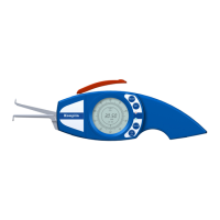
Illustrates specific models of Kroplin internal measuring gauges.
Depicts various models of Kroplin internal measuring gauges.
The primary visual output screen for measurements and settings.
Buttons used to control the device functions and settings.
Details the movable and fixed arms used for measurement.
Access point for replacing the device's power source.
Lever used to open and close the measuring jaws.
Points of contact on the measuring arms that touch the workpiece.
Shows relative measurements, switching from absolute mode.
Finds and saves the minimum measured value.
Finds and saves the maximum measured value.
Saves the measured value for a short period.
Activates tolerance marks and tolerance display (red/green LED).
Activates the setup menu for configuration.
Displays measured values in millimeters.
Displays measured values in inches.
LEDs indicate if measured value is within or out of tolerance.
Notes on short vs. long key presses for operations.
Selects measuring programs and adjusts tolerance limits/scale.
Starts SETUP menu, OFFSET, tolerance, and unit selection.
Transfers data, adjusts tolerance/zero point, and locks keys.
Switches device on/off and toggles between absolute/relative modes.
Procedure for turning the device on and off.
How to change between absolute and relative measurement modes.
Details on selecting MIN, MAX, HOLD, and TOL measuring programs.
How to start and navigate the SETUP menu for configurations.
Steps to perform zero point adjustment (OFFSET) on the device.
How to set upper and lower tolerance limits in Absolute mode.
How to set upper and lower tolerance limits in Relative mode.
Procedure for changing the measuring unit between MM and INCH.
How to select and change the scale interval for measurements.
Procedure for locking and unlocking the device's keys.
How to protect measuring contacts during measurement.
Ensuring accuracy by using a ring gauge and performing resets.
Descriptions for input, tolerance, OFFSET, and REL-MODE errors.
Indicates when the battery needs replacement.
Specifies battery type and emphasizes correct polarity during replacement.
Step-by-step guide for safely changing the device battery.
Details on Mitutoyo-Digimatic and USB interfaces.
Information about the accessory for holding the device.
Details range, scale interval, errors, and force for F102-F270 models.
Covers measuring programmes, temperature, display, power, and interface.
Details range, scale interval, errors, and force for F415-F640 models.
Covers measuring programmes, temperature, display, power, and interface.
Details on repair, replacement, and exclusions for warranty claims.
States compliance with EMC directive for electromagnetic compatibility.
| Brand | Kroeplin |
|---|---|
| Model | F205 |
| Category | Test Equipment |
| Language | English |