Do you have a question about the KROHNE DW 181 and is the answer not in the manual?
Crucial safety guidelines for installation and operation.
Overview of the standards and directives the product complies with.
Specific safety measures for hazardous area installations.
Guidelines for safe handling and transport of the device.
Details on product liability, warranty terms, and conditions.
List of supplied items and documentation provided with the product.
Information on official certifications and approvals for the product.
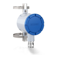
Exploded views and identification of key components for different versions.
Explanation of standard and supplementary equipment labels.
Explanation of the product's type code and its elements.
Guidance on optimal positioning within the piping system.
Specific instructions for installing in ATEX/hazardous zones.
Steps for securely connecting the device to the pipeline.
Importance of indicating and respecting flow direction.
Basic guidelines for starting and commissioning the flow switch.
Procedure for adjusting limit switches on standard and EEx ia versions.
Specific steps for adjusting limit switches with Type G indicator.
Specific steps for adjusting limit switches with Type A indicator.
Procedure for adjusting limit switches on EEx d versions.
Detailed instructions for adjusting the MS 12/BRX switch.
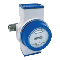
Description of Indicator G and Indicator A for local flow display.
Overview of available limit switches and their ratings.
Technical specifications for the EEx d switch version.
Technical specifications for the high-temperature (non-EEx) version.
Information on the tropical version's junction box and plug.
Instructions for cleaning and basic maintenance.
Diagrams showing disassembled components for various models.
Steps for inspecting the measuring assembly and housing.
Detailed checks for the measuring system, cone-disc, and spring.
Procedure for inspecting the housing of DW181 and DW182 models.
Customer-accessible servicing tasks.
Guide to repositioning the dial on Type A indicators.
Instructions for removing the display assembly for fault diagnosis.
Steps to clean springs or change the measuring system sub-assembly.
Procedure for replacing gaskets in DW 183 flow controllers.
Detailed flow rate ranges for DW 181, 182, 183, and 184 models.
Specifications for standard and HT versions' temperature resistance.
Special conditions and markings for ATEX certified versions.
Ratings and characteristics for various limit switch types.
Details on materials used for different instrument versions.
Explanation of measuring systems C, E, and P.
Details on the DW 183 model's application and characteristics.