Do you have a question about the KROHNE OPTIFLUX 2000 and is the answer not in the manual?
Explains danger, warning, caution, and information symbols used in the manual.
Details requirements for trained personnel and adherence to local safety directives.
States user responsibility for suitability and intended use, and supplier's limitations.
Directs users to CD-ROM, datasheets, manuals, and website for further information.
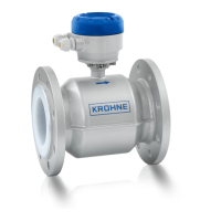
Lists the components included in the product package, including flowmeter and documentation.
Advises checking device nameplate for order confirmation and supply voltage.
Provides guidelines for storing the device in a dry, dust-free location, away from sunlight.
Specifies recommended straight pipe sections before and after the flowmeter.
Illustrates permissible and impermissible mounting orientations for the flowmeter.
Defines the maximum permissible deviation for pipe flange faces during installation.
Specifies the required distance from T-sections to the flowmeter installation.
Illustrates how to avoid vibrations that could affect the device.
Advises avoiding strong magnetic fields near the flowmeter installation.
Shows correct and incorrect installations relative to pipe bends.
Illustrates proper installation before an open discharge pipe.
Shows correct and incorrect installation positions relative to a control valve.
Details requirements for air venting and points for proper installation.
Shows recommended installation position after a pump.
Provides process and ambient temperature limits for different sensor and liner types.
Lists minimum operating pressures (vacuum loads) for various diameters and liner materials.
Explains the multi-step bolt tightening procedure and torque application.
Details crucial safety precautions for electrical work, including power disconnection and trained personnel.
Explains the importance of proper grounding for personnel safety against electric shocks.
Describes different grounding rings, their specifications, and applications.
Explains conditions and requirements for using virtual reference with specific IFC versions.
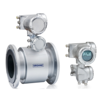
Provides schematic diagrams and explanations for connecting the sensor and field housing.
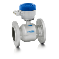
Details dimensions and weight for different versions of the OPTIFLUX 2000 sensor.
| Measuring Principle | Electromagnetic |
|---|---|
| Process Temperature | -40°C to +180°C |
| Output Signal | 4...20 mA, pulse, frequency |
| Communication | HART, PROFIBUS PA, FOUNDATION Fieldbus |
| Power Supply | 100...230 VAC, 24 VDC |
| Protection Class | IP67 |
| Material | Stainless steel, PTFE |
| Accuracy | ±0.2% of reading ±1 mm/s |