GB-5
GB
? No direct current although the flame is burning.
! The UV sensor is dirty, e.g. sooted.
• Clean sensor or quartz glass.
! Humidity inside the UV sensor.
• Vent sensor.
! The distance between the UV sensor and the
flame is too great.
• Reduce the distance.
? The automatic burner control unit ignites in pulses.
! The sensor “sees” the ignition spark.
• Reposition the UV sensor so that it cannot “see”
the ignition spark.
• Use an automatic burner control unit that is able
to distinguish between an ignition spark and a
flame signal.
? The intensity of the flame signal decreases after
a longer period of operation.
! UV tube fault due to incorrect UV sensor connec-
tions.
• Remove the UV sensor and return for repair.
• Connect the UV sensor in accordance with the
wiring instructions.
? The automatic burner control unit performs a fault
lock-out during start-up or operation.
! The highly fluctuating flame signal temporarily
exceeds the switch-off threshold.
• Reduce the distance between UV sensor and
flame.
• Position the UV sensor so that it can “view” the
flame without hindrance (e.g. smoke curtain).
• Replace quartz glass disc in the UV sensor with
a lens (see “Accessories”).
! The switch-off threshold in the automatic burner
control unit is set too high, e.g. BCU, PFU or
IFD258.
• Adjust switch-off threshold.
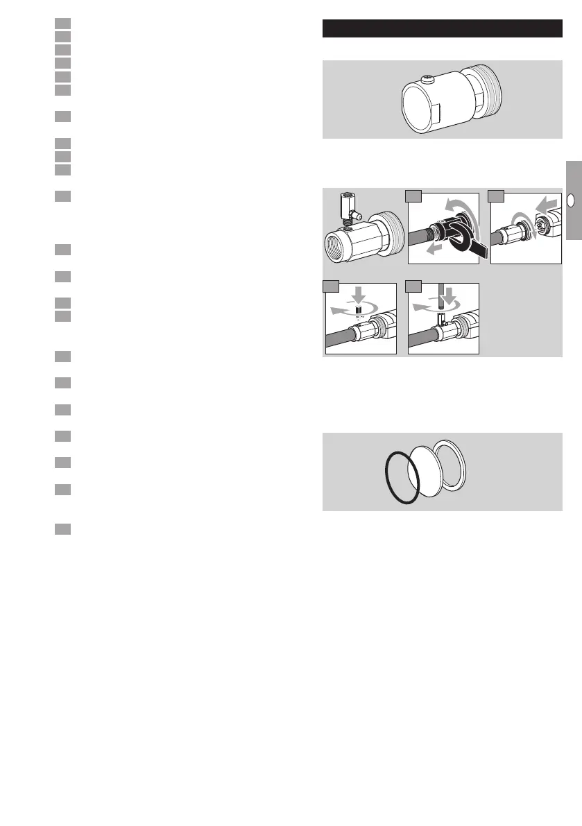
Accessories
Adapter UVS 1 with quartz glass disc
Order No.: 7 496 061 5
Installation, see “Installation”.
Cooling air adapter with quartz glass disc
2
3 4
1
Rp 1/2, Order No.: 7 496 061 4
1/2 NPT, Order No.: 7 496 061 3
Nozzle for cooling air adapter, Order No.:
74960616
Quartz glass lens with seals
Order No. 7 496 061 1