Do you have a question about the Kruger Ecowatt K320 Series and is the answer not in the manual?
Overview of the safety precautions chapter, emphasizing careful reading and adherence.
Defines key safety terms like Danger, Warning, Note, and trained professionals.
Explains warning symbols used to caution about hazards and how to avoid them.
Provides essential safety guidelines for operating and maintaining the VFD.
Guidelines for safe delivery, handling, and installation of the VFD.
Safety precautions for VFD commissioning, wiring, and operation.
Safety measures for VFD maintenance, inspection, and component replacement.
Instructions for proper disposal and recycling of the VFD at the end of its lifecycle.
Introduction to basic installation and commissioning rules for quick setup.
Steps for inspecting the product after receiving it to ensure it's undamaged and complete.
Checks to perform before applying the VFD, including load, current, and grid voltage.
Checks related to the installation environment before actual installation and use.
Confirmation checklist for VFD installation, including cables, clearance, and grounding.
Steps for basic commissioning before the VFD's actual use.
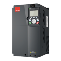
Overview of operation principles, product features, layouts, and model designation rules.
Explains the basic operating principle of the VFD and its main circuit diagram.
Detailed specifications of the VFD, including power input, output, and technical performance.
Description of the information found on the VFD product nameplate.
Explanation of the VFD model designation code structure.
Table listing product ratings for different VFD models.
Diagram illustrating the VFD structure with numbered components.
Introduction to mechanical and electrical installation procedures for the VFD.
Detailed guidance on the mechanical aspects of VFD installation.
Requirements for the installation environment to ensure optimal VFD operation.
Guidelines on the correct vertical installation of the VFD for optimal heat dissipation.
Description of the three installation modes: wall-mounting, flange-mounting, and floor-mounting.
Diagram and notes for single-unit VFD installation, including clearance dimensions.
Diagram and notes for installing multiple VFDs in parallel, with clearance dimensions.
Details on vertical installation, emphasizing the use of windshields for proper heat dissipation.
Guidelines for tilted installation, ensuring separation of air inlet and outlet ducts.
Diagrams and procedures for wiring the main circuit of the VFD.
Wiring diagrams for main circuits of different VFD models.
Diagrams illustrating the main circuit terminal connections for various VFD models.
Step-by-step procedure for wiring the main circuit terminals of the VFD.
Diagrams and descriptions for standard control circuit wiring.
Schematic diagram of the basic control circuit wiring for the VFD.
Diagram for connecting input/output signals, including U-type short connector usage.
Measures for protecting VFD and cables against short circuits and overload.
Protection methods for VFD and input power cables against short circuits.
Protection methods for motor and motor cables against short circuits.
Measures to protect the motor from thermal overload.
Information on bypass connection for system operation during VFD faults.
Overview of how to operate the VFD using the keypad.
Introduction to the LCD keypad and its functions for VFD control.
Explanation of VFD keypad display interfaces in stop and running states.
Detailed guide on operating the VFD using the keypad interface.
Diagrams illustrating how to enter and exit menus on the VFD keypad.
How to add, shift, or delete monitoring items from parameter lists.
Procedure for adding parameters to the stop or running state display lists.
Method for adding parameters to the common parameter setup list.
Interface for selecting and editing parameter values, showing authority and default values.
Interface for editing parameter values, including bit-wise settings and saving.
Interface for real-time monitoring of detected parameter values.
Procedure for performing motor parameter autotuning for optimal control.
How to back up and restore VFD parameters to different storage areas.
Interface for system setup, including language, time, and backlight settings.
Guidance for initial VFD setup, including parameter setting and autotuning.
Introduction to the VFD's internal function modules and basic operations.
Overview of the VFD's function modules.
Step-by-step procedure for common VFD commissioning, including motor setup.
Explanation of vector control technology for asynchronous and synchronous motors.
Description of space voltage control and V/F curve modes for motor control.
Explanation of VFD's torque control capabilities and limitations.
Guidance on setting motor parameters and performing autotuning for accurate control.
Description of VFD start/stop modes: start frequency, DC braking, speed tracking.
Methods for setting frequency using main and auxiliary reference channels.
Details on VFD analog input terminals (AI1, AI2) and HDI input terminals.
Description of VFD analog output terminals (AO1) and high-speed pulse output (HDO).
Information on VFD's programmable digital and HDI input terminals.
Details on VFD's relay output terminals (RO1, RO2) and open collector output (Y).
Explanation of the VFD's simple PLC function for multi-step speed control.
Configuration of 16-step speeds using multi-step speed terminals.
Guidance on PID control for process control, including parameter setup.
Description of the wobbling frequency function for specific industrial applications.
Functionality of the VFD's local encoder input using HDI high-speed pulse port.
Procedures for commissioning closed-loop vector, position, and spindle positioning control.
Guidelines for identifying, diagnosing, and resolving VFD faults.
Overview of the chapter listing all function codes and their descriptions.
Comprehensive list of VFD function codes, parameters, defaults, and modify status.
Introduction to fault reset, fault history, and VFD fault analysis.
How to interpret VFD fault indicators and displayed fault codes.
Methods for resetting faults on the VFD using keypad or power.
Information on how fault types and running data are recorded.
General steps to handle VFD faults and confirm corrective measures.
Detailed table listing fault codes, possible causes, and corresponding solutions.
Information on other operational states such as system power failure (PoFF).
Analysis and troubleshooting for common VFD faults.
Troubleshooting flowchart for when the motor fails to work.
Troubleshooting flowchart for motor vibration or unusual noise.
Troubleshooting steps for overvoltage faults in the VFD.
Troubleshooting steps for undervoltage faults in the VFD.
Troubleshooting steps for unusual motor heating.
Troubleshooting steps for VFD overheating issues.
Troubleshooting steps for motor stalls during acceleration.
Troubleshooting steps for overcurrent faults in the VFD.
Measures to address common interference issues affecting VFD operation.
Solutions for interference affecting sensors and meters connected to the VFD.
Measures to resolve interference issues with RS485 communication.
Troubleshooting stop failures and indicator issues caused by motor cable coupling.
Solutions for RCD misoperation caused by VFD leakage current.
Troubleshooting steps for sensible voltage on the VFD chassis.
Overview of carrying out preventive maintenance on the VFD.
Routine maintenance checks for ambient environment, voltage, keypad, and main circuit.
Information on the cooling fan's service life and replacement procedure.
Information on capacitor reforming and replacement procedures.
Instructions for reforming DC bus capacitors after long periods of inactivity.
Guidelines for checking power cable connections and ensuring proper installation.
Overview of communication protocols supported by the VFD, including Modbus.
Explanation of the Modbus protocol, its transmission modes, and network structure.
Details on VFD application using Modbus RTU mode via RS485 interfaces.
Description of RS485 interface operation, wiring, and transmission distance.
Modbus wiring diagram for a network with a single VFD and PC.
Common connection methods (chrysanthemum, star) for networks with multiple VFDs.
Details on the RTU communication mode and its frame structure.
Description of the RTU data frame structure, including start, data, and CRC domains.
Explanation of error check methods like odd/even check and CRC for RTU frames.
Description of RTU command codes and communication data formats.
Format for reading multiple contiguous data words from the VFD using 03H command.
Format for writing single data words to VFD parameters using 06H command.
Command code 08H for querying VFD circuit detection information.
Format for writing multiple data words to VFD parameters using 10H command.
Rules for defining communication data addresses and function code address formats.
Explains the two-byte address format for function codes (group and parameter).
Describes addresses for VFD control commands and status monitoring.
Explanation of fieldbus scale for representing decimal values in hexadecimal form.
Table describing error message codes and their definitions for communication errors.
Examples of read (03H) and write (06H, 10H) commands for VFD communication.
Examples of reading VFD status words and fault information.
Examples of writing parameters like forward running and max output frequency.
Example of continuously writing multiple parameters like ACC/DEC time.
Step-by-step guide for Modbus communication commissioning using PC software.
Common communication faults and their possible causes.
Explanation of the model definition structure for expansion cards.
Information on expansion card dimensions and the general installation process.
Diagrams and instructions for grounding and wiring expansion cards.
Detailed terminal function description and specifications for the IO expansion card.
Description of the programmable expansion card's terminals and features.
Function descriptions for various communication expansion cards.
Functionality and indicators for Bluetooth/WIFI communication cards.
Details on the PROFIBUS-DP communication card, including connector pinout.
Functionality and indicators for the Ethernet communication card.
Description of CANopen and CAN master/slave communication cards.
Functionality and indicators for the PROFINET communication card.
Function descriptions for various PG expansion cards.
Details on the Sin/Cos PG card, including terminals and indicator functions.
Description of the UVW incremental PG card's terminals and functions.
Details on the Resolver PG card, including terminals and indicator functions.
Description of the multifunction incremental PG card's terminals and features.
Details on the 24V multi-function incremental PG card's terminals and indicators.
Description of the simplified incremental PG card's terminals and indicators.
Overview of the chapter covering VFD technical data and certifications.
Information on VFD capacity, derating due to temperature, altitude, and carrier frequency.
Guidelines for selecting VFD models based on motor capacity and rated current.
Factors requiring VFD derating: temperature, altitude, and carrier frequency.
Derating coefficients based on ambient temperature exceeding 40°C.
Derating guidelines for VFDs installed at altitudes exceeding 1000m.
Derating guidelines when carrier frequency exceeds the factory setting.
Specifications related to grid voltage, short-circuit capacity, and frequency.
Data related to motor connection, including type, voltage, protection, and frequency.
List of standards the VFD complies with, including safety and EMC standards.
Information on EMC requirements for VFDs and application environment categories.
Stipulations for induction disturbance limits meeting Category C2 requirements.
Stipulations for induction disturbance limits meeting Category C3 requirements.
Overview of the chapter describing VFD dimension drawings.
Diagram illustrating the structure of the VFD keypad and installation bracket.
Detailed diagram of the VFD keypad structure.
Information on installing external keypads using brackets or screws.
Diagram showing the VFD structure with all components.
Detailed structural information and dimensions for VFD mounting.
Dimensions for wall-mounting VFD models.
Dimensions for flange installation of VFD models.
Dimensions for floor installation of VFD models.
Overview of selecting optional accessories for the VFD.
External wiring diagrams for common VFD accessories.
Guidelines for ensuring VFD voltage class consistency with the grid.
Recommendations for selecting and arranging power, control, and shielded cables.
Requirements for input power and motor cable sizing, temperature, and grounding.
Guidelines for selecting and arranging analog, digital, and relay control cables.
Table of recommended cable sizes and screw tightening torques for VFD models.
Guidelines for arranging motor, power, and control cables to minimize interference.
Procedures for checking motor and motor cable insulation resistance.
Requirements for selecting and configuring circuit breakers and contactors.
Selection guidelines for input, DC, and output reactors based on VFD models and conditions.
Information on input and output filters for reducing VFD interference.
Description of filter model identifiers, including series, type, voltage, and current.
Table for selecting appropriate input and output filters for VFD models.
Information on selecting and installing braking components like resistors and units.
Guidelines for selecting brake components based on load characteristics and VFD models.
Recommendation to use shielded cables for braking resistor connections.
Instructions for installing braking resistors, including cooling and material considerations.
Description of the STO function logic and its input states.
Table describing trigger and indication delays for STO channels.
Checklist for ensuring proper installation and use of the STO function.
Contact information for product queries and service support.
Information on how to provide feedback or comments on VFD manuals.
Guidance on finding VFD manuals and product documents online.
| Number of speeds | 3 |
|---|---|
| Number of Fan Speeds | 3 |
| Filter Type | Aluminum grease filter |
| Material | Stainless steel |
| Installation | Wall-mounted |
| Grease filter type | Aluminum |
| Airflow | 320 m³/h |