Do you have a question about the KSB SMARTRONIC MA R1310 and is the answer not in the manual?
Explanation of the digital positioner's control mechanism using PWM technology.
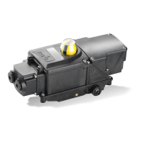
Comprehensive list of technical specifications for the SMARTRONIC MA, including electrical and pneumatic data.
Details on connecting the pneumatic air supply to the SMARTRONIC MA unit.
Configuration of the safety position (stop, open, or close) when power is lost.
How to connect the positioner to the 4-20 mA control signal loop.
Guide to performing auto-calibration for optimal adjustment of the positioner.
Conditions and steps for initiating the auto-calibration sequence.
How to adjust the cams for the end stop sensors if actuator stops are modified.
Manually adjusting the positioner's opening/closing stroke and validating settings.
Manually adjusting the dead band parameters for improved stability or accuracy.
Manually adjusting the positioner gain for optimal response time and stability.
Defining current values (I1, I2) for position setpoints (P1, P2) for direct/indirect action.
Configuring the safety position (UNDEF, STOP, CLOSE, OPEN) upon loss of electrical power.
Configuring autocalibration status, regulator gain, and dead band.
Defining the valve's safety position on loss of electrical supply.
Troubleshooting steps for display issues on power up, including wiring and contrast checks.
Diagnosing and resolving issues where the positioner does not respond to the 4-20mA signal.
| Brand | KSB |
|---|---|
| Model | SMARTRONIC MA R1310 |
| Category | Valve Positioners |
| Language | English |