Do you have a question about the KTR ROTEX GS Series and is the answer not in the manual?
Guidance on selecting the appropriate coupling based on application requirements and standards.
Provides general recommendations and safety notes for installation and operation.
Provides essential safety and advice notes regarding operation and handling.
Highlights critical dangers associated with assembly, operation, and maintenance.
Defines the authorized conditions and requirements for assembling, operating, and maintaining the coupling.
Details dimensions and specifications for standard shaft coupling configurations.
Technical specifications and dimensions for clamping hub types.
Dimensions for clamping ring hubs of types 6.0, 6.0 steel, and 6.0 light.
Dimensions and specifications for the DKM coupling type.
Dimensions and specifications for the Compact coupling type.
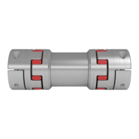
Illustrates and describes the different types of hubs available for the ROTEX® GS coupling.
Lists and illustrates the standard components of ROTEX® GS couplings.
Provides detailed instructions and important considerations for the assembly process.
Offers critical advice and warnings regarding the machining of coupling bores.
Details the assembly process for hub types 1.0, 1.1, and 1.2.
Explains the assembly steps for various types of clamping hubs.
Provides instructions for assembling clamping ring hubs of types 6.0, 6.0 steel, 6.0 light, and 6.5.
Details displacement figures for proper alignment and their impact on coupling life.
Provides essential guidance for using the coupling in hazardous environments.
Details how to use the couplings safely and compliantly in hazardous locations.
Specifies control and maintenance intervals for couplings used in hazardous areas.
Provides guidelines on acceptable wear limits for coupling components.
Lists materials suitable for use in hazardous areas.
Explains the specific markings indicating suitability for hazardous area applications.
Provides instructions and checks required before initial operation of the coupling.
Details common breakdowns, their causes, and recommended elimination procedures.
Presents the EC Certificate of Conformity for the ROTEX® GS couplings.
| Type | Jaw Coupling |
|---|---|
| Series | GS |
| Backlash | Zero Backlash |
| Compensation Capabilities | Axial, radial, and angular misalignment |
| Material (Hubs) | Steel |
| Temperature Range | -50 °C to +120 °C |
| Application | pumps, compressors |
| Features | Vibration damping |
| Material (Spider) | Polyurethane (T-PUR) |