EasyManua.ls Logo

KTR ROTEX GS User Manual

KTR ROTEX GS
36 pages
To Next Page IconTo Next Page
Page #1 background imageLoading...
Page #1 background image
KTR Kupplungstechnik
GmbH
D-48407 Rheine
ROTEX
®
GS
Operating/mounting instructions
KTR-N
Sheet:
Edition:
45510 EN
1of36
15
Please note protection
mark ISO 16016.
Drawn: 15.10.12 Pz Replaced for: KTR-N valid from 08.02.12
Verified: 29.10.12 Pz Replaced by:
ROTEX
®
GS
Torsionally flexible jaw couplings types:
shaft coupling, clamping hubs, clamping ring hubs,clamping ring hubs light,
DKM, Compactand their combinations
according toStandard 94/9/EC (ATEX 95)
for finish bored, pilot bored and unbored couplings
ROTEX
®
GS, shaft coupling ROTEX
®
GS, DKM
ROTEX
®
GS, clamping hubs ROTEX
®
GS, Compact
ROTEX
®
GS, clamping ring hubs
ROTEX
®
GS, clamping ring hubs steel
ROTEX
®
GS, clamping ring hubs light
Expansion hubs and their combinations
for finish bored, pilot bored and unbored couplings
ROTEX
®
GS, expansion hubs

Other manuals for KTR ROTEX GS

Question and Answer IconNeed help?

Do you have a question about the KTR ROTEX GS and is the answer not in the manual?

KTR ROTEX GS Specifications

General IconGeneral
Material (Hub)Steel
Nominal Torque Range2.5 Nm to 25, 000 Nm
Shaft Diameter6 mm to 180 mm (depending on size)
BacklashZero Backlash
Compensation CapabilitiesAngular, and Axial Misalignment

Summary

Technical Data

Standard Shaft Coupling

Technical specifications and dimensions for the standard shaft coupling type.

Clamping Hubs

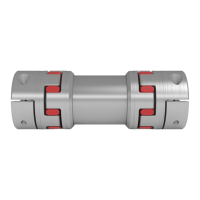
Technical specifications and dimensions for ROTEX® GS clamping hubs.

Hints

2.1 Coupling Selection

Guidelines for selecting the appropriate ROTEX® GS coupling based on application requirements.

2.3 Safety and Advice Hints

Critical safety warnings, dangers, and important advice for users.

2.4 General Hint to Danger

General safety instructions to prevent unintentional engagement and injury.

Assembly

4.3 Hints for Assembly

General guidelines and precautions for the assembly process of ROTEX® GS couplings.

4.9 Displacements – Alignment of the Couplings

Guidelines and figures for aligning couplings and managing displacements.

Enclosure A

Hints and Instructions Regarding the Use in Hazardous Areas

Specific guidelines for using ROTEX® GS couplings in hazardous environments.

5.1 Use in Hazardous Areas According to the Regulations

Regulations and conditions for operating couplings in hazardous industrial locations.

5.2 Control Intervals for Couplings in Hazardous Areas

Recommended inspection intervals for couplings used in hazardous areas.

5.5 Marking of Coupling for the Hazardous Area

Explanation of markings on couplings indicating suitability for specific hazardous area conditions.

5.7 Breakdowns, Causes and Elimination

Troubleshooting guide for common breakdowns, their causes, and elimination methods.

Related product manuals