KTR Kupplungstechnik
GmbH
D-48407 Rheine
ROTEX
®
GS
Operating/mounting instructions
KTR-N
Sheet:
Edition:
45510 EN
31of36
15
Please note protection
mark ISO 16016.
Drawn: 15.10.12 Pz Replaced for: KTR-N valid from 08.02.12
Verified: 29.10.12 Pz Replaced by:
Hints and Instructions Regarding the Use in Hazardous Areas
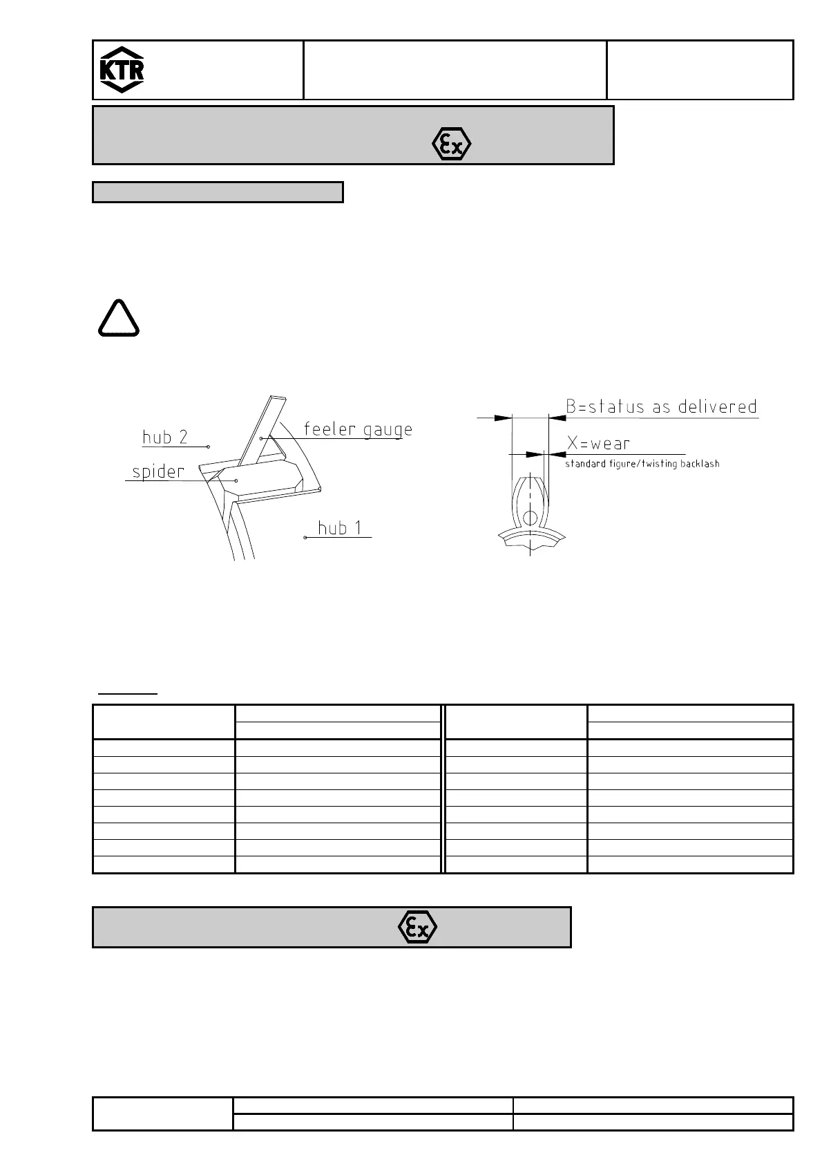
5.3 Approximate Values of Wear
In case of a backlash of more than x mm, the flexible spider must be exchanged.
Whether the limit for replacement has been achieved or not depends on the conditions of operation and the
existing operating parameters.
In order to ensure a long lifetime of the coupling and avoid danger with the use in
hazardous areas, the shaft ends have to be aligned accurately. Please make absolutely sure
to adhere to the displacement figures mentioned (see table 13 and 14). If these figures are
exceeded, the coupling will be damaged.
Illustration 29: checking of the limit of wear Illustration 30: wear of spider
For backlash-free applications no wear is permitted, since otherwise the operating principle
of the coupling (backlash-free condition) is no longer ensured. If a backlash-free operation
is not required, the following figures apply:
Table 15:
ROTEX
GS
Size
Wear limits
ROTEX
GS
Size
Wear limits
X
[mm] X
[mm]
5 0,4 38 1,7
7 0,5 42 2,0
9 0,9 48 2,25
12 0,6 55 2,50
14 1,25 65 2,75
19 0,9 75 3,00
24 1,0 90 3,25
28 1,4
5.4 Permissible Coupling Materials in the Hazardous Area
In the Explosion Groups IIA, IIB and IIC the following materials may be combined:
steel
stainless steel
aluminium wrought products
Semifinished products from aluminium with a magnesium part of up to 7,5 % and a yield point of
R
p0,2
≥ 250 N/mm
2
are permitted for the use in hazardous areas.
Aluminium diecast is generally excluded for hazardous areas.