KTR Kupplungstechnik
GmbH
D-48407 Rheine
ROTEX
®
GS
Operating/mounting instructions
KTR-N
Sheet:
Edition:
45510 EN
17of36
15
Please note protection
mark ISO 16016.
Drawn: 15.10.12 Pz Replaced for: KTR-N valid from 08.02.12
Verified: 29.10.12 Pz Replaced by:
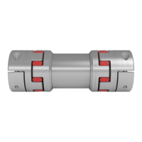
Features of the standard spiders
Spider hardness
(Shore)
80 Sh-A-GS 92 Sh-A-GS 95/98 Sh-A-GS
64 Sh-D-H-GS
64 Sh-D-GS
72 Sh-D-H-GS
72 Sh-D-GS
Size
5 - 24 5 - 55 5 - 90 7 - 38 42 - 90 24 - 38 42 - 65
Material
Polyurethane Polyurethane Polyurethane Hytrel
Poly-
urethane
Hytrel
Poly-
urethane
Marking
(colour)
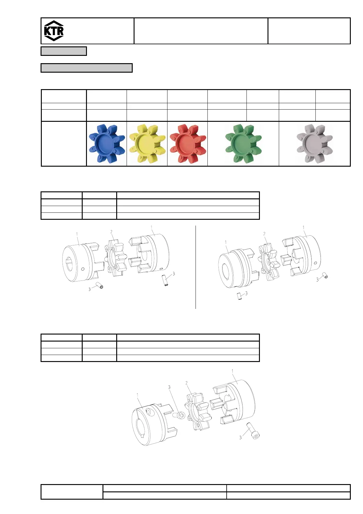
Components of ROTEX
®
GS, backlash-free shaft couplings
1 2 hub
2 1 spider
3 2 setscrewDIN EN ISO 4029
Illustration 12: ROTEX
®
GS, size 5 - 38 Illustration 13: ROTEX
®
GS, size 42 - 90
Components of ROTEX
®
GS, clamping hubs
1 2 clamping hub (hub type 2.0, 2.1, 2.5 or 2.6)
2 1 spider
3 2 cap screwsDIN EN ISO 4762
Illustration 14: ROTEX
®
GS, clamping hub
Clamping hubs type 2.0 and 2.5 without keyway are not permissible for applications according to
DIN EN ISO 13849, part 2.