KTR Kupplungstechnik
GmbH
D-48407 Rheine
ROTEX
®
GS
Operating/mounting instructions
KTR-N
Sheet:
Edition:
45510 EN
14of36
15
Please note protection
mark ISO 16016.
Drawn: 15.10.12 Pz Replaced for: KTR-N valid from 08.02.12
Verified: 29.10.12 Pz Replaced by:
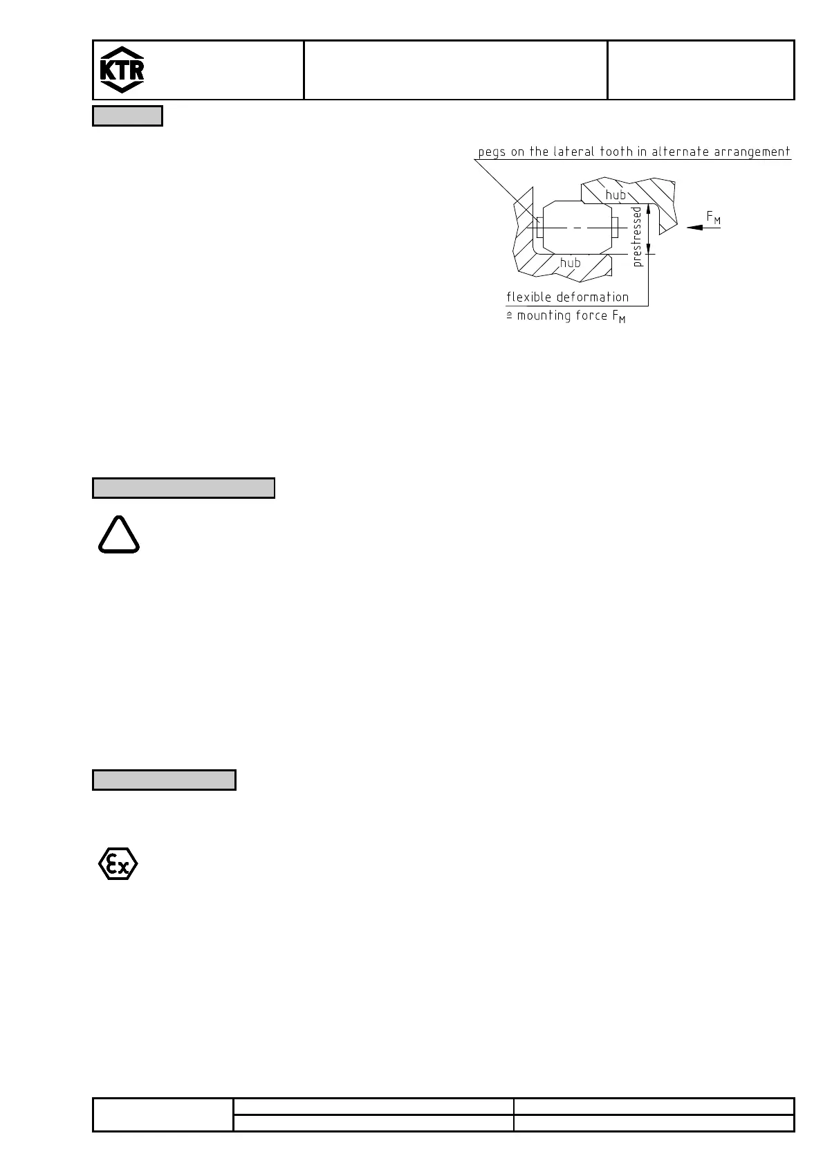
The
coupling was developed for a backlash-
free power transmission and easy plug-in assembly. This
backlash-free power transmission is realized in the range
of prestress (see illustration10). The big concave surface
contact results in a lower surface pressure on the involute
tooth. Consequently the tooth can be overloaded many
times over with no wear/deformation.
The safe operation in the range of prestress is ensured,
because the coupling operates according to the principle of
the positive-locking rubber spring prestress with high
damping features. The star-shape coupling spider is
inserted into the cams of the hubs which are machined
specifically accurately with a small amount of prestress,
resulting in the necessary backlash-free power
transmission.
Illustration 10: prestress of spider
The flexible teeth compensating for misalignments are radially supported in the internal diameter by means of a
web. An external deformation is limited by the concave shape of the cams, ensuring a smooth operation even
with bigger masses (e. g. steel mills, articulated arms, etc.). The flexible spiders for the GS series are available in
five different kinds of Shore hardness, injected in different colours, either as a torsionally soft or hard material.
For a long-term smooth operation of the coupling the coupling has to be selected based on
the selection standards applying for the application (in accordance with DIN 740, part 2)
(see ROTEX
®
GS catalogue).
In case that the operating conditions change (power, speed, modifications on engine and
machine) it is absolutely necessary to verify the coupling selection.
Please note that the technical details concerning the torque refer to the spider only. The
transmittable torque of the shaft-hub-connection has to be reviewed by the customer and is
subject to his responsibility.
For drives subject to dangerous torsional vibrations (drives with periodical torsional vibration load) it is necessary
to perform a torsional vibration calculation to ensure a safe operation. Typical examples of drives subject to
dangerous torsional vibrations are drives with diesel engines, piston pumps, piston compressors, etc. If requested,
KTR will perform the coupling selection and torsional vibration calculation.
Please read through these mounting instructions carefully before you set the coupling into operation.
Please pay special attention to the safety instructions.
The
coupling is suitable and approved for the application in hazardous areas.
For the use of couplings in hazardous areas please note the special safety hints and regulations as
per appendix A.
In order to ensure the operating principle of ROTEX
®
GS and avoid an early wear of the coupling, a
corresponding torsional stiffness factor „Sd“ has to be considered for the selection, each depending on the
application (see catalogue). Temperatures and shocks are provided with the corresponding factors, too (see
catalogue).
The mounting instructions are part of your product. Please keep them carefully and close to the coupling. The
copyright for these mounting instructions remains with KTRKupplungstechnik GmbH.